

We have a Hallowe’en-themed electronic project for you: a motion-activated “screaming” audio generator for your Jack O’Lantern or other spooky decoration.
Ghosts, goblins and integrated circuits? Electronic devices are a fairly common part of Hallowe’en today, so let’s make one ourselves!
By connecting a Passive Infrared Sensor (PIR) to a relay that controls an oscillator connected to a speaker and an LED, we can create an electronic monster of sorts to scare unwary trick-or-treaters, or the neighbourhood alley cat. Let’s take a look at how it works.
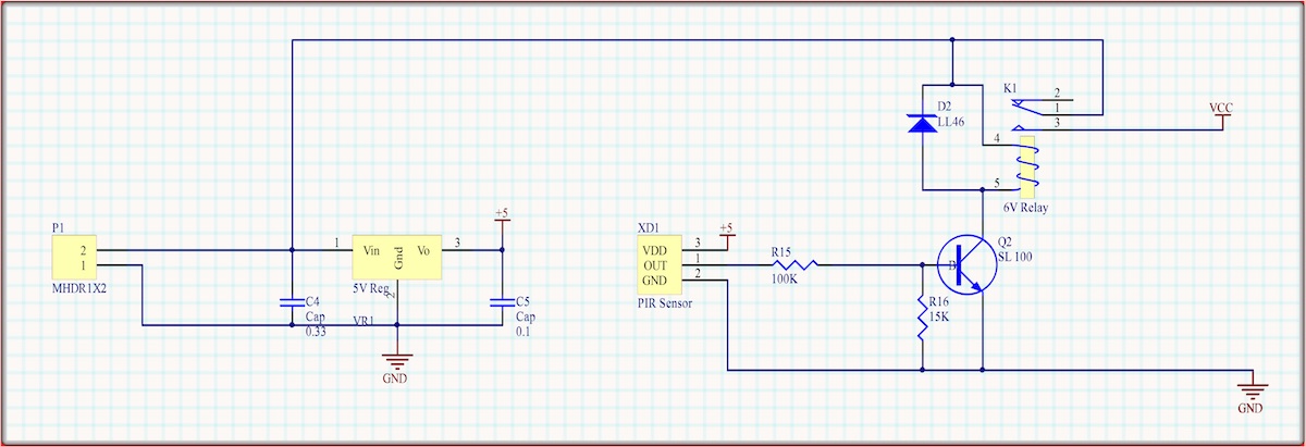
The Screaming Jack circuit consists of four basic sections. The first is a power supply of a 9-volt battery connected to P1 this leads to a 7805 voltage regulator which provides power to the Passive Infrared Detector and the two Dual op-amps.
The sound circuit is enabled when the PIR detects motion causing the OUT to go to 2.5V turning the transistor on and the relay to close.
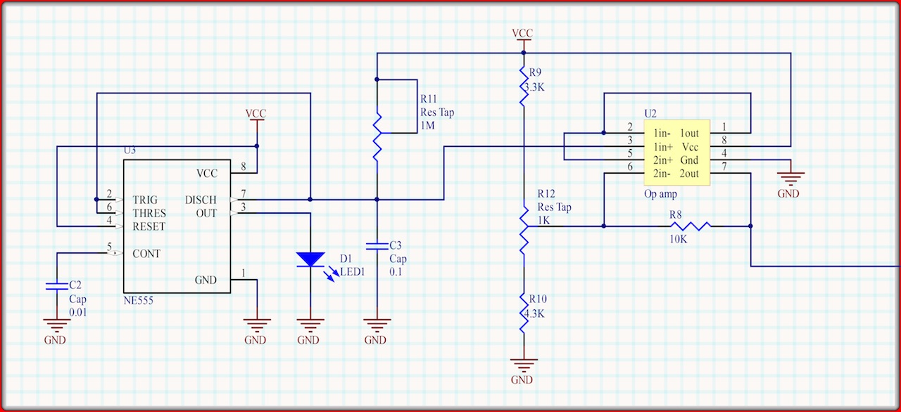
U2 LMC662 is a dual op-amp creating a saw-tooth waveform that drives the voltage controlled oscillator. This circuit contains a NE555 timer (U3) that outputs a square wave to drive the generator circuit. There are two controls for this circuit, R11 which controls the frequency and R12 which controls the waveform.
An operational amplifier (op-amp) is a high-gain electronic voltage amplifier with a differential input and a single-ended output. It is designed to provide an output that is hundreds of thousands of times larger than the potential difference between its input terminals. They have their origins in analog computers, where they were used to perform mathematical operations. Op-amps are some of the most widely used electronic components used today, present in a vast number of electronic devices.
The 555 timer IC is an integrated circuit used as an oscillator. Introduced in 1972 by Signetics, the 555 is still in widespread use due to its low price and stability, and is the most popular integrated circuit ever manufactured.
Passive Infrared Sensors work by detecting heat energy radiating from objects. When the level of radiation received by the sensor changes, it assumes that the objects in front of it have changed, eg. something has moved.
The output frequency is determined by the values of R and C. F = 1.44/RC.
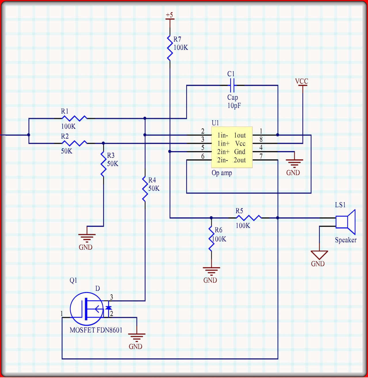
The voltage controlled oscillator U1 outputs a square wave at a frequency proportional to the input from the saw-tooth generator.

The output gets feed back to the FET which acts as a switch to the first op-amp. The higher the voltage on the input the higher the frequency for the square wave output. The two 50K resistors in op-amp1 act as a voltage divider holding the non-inverting input to ½ of the signal voltage. The inverting input is driven by the n-MOSFET that is turned on by the Audio Out. When the two voltages are equal then the op-amp turns on to drive the inverting input of the second op-amp. The non-inverting input of the second op-amp is held at 3.33 volts until the inverting input matched that voltage putting the output low. This drops the non-inverting input to 1.66 volts and when the waveform from op-amp1 reaches 1.66 as well the op-amp turns on again.
By attaching the LED, speaker and motion sensor to wires, you can put the board someplace else (like in a cigar box under the pumpkin) and run them into the pumpkin or other decoration.
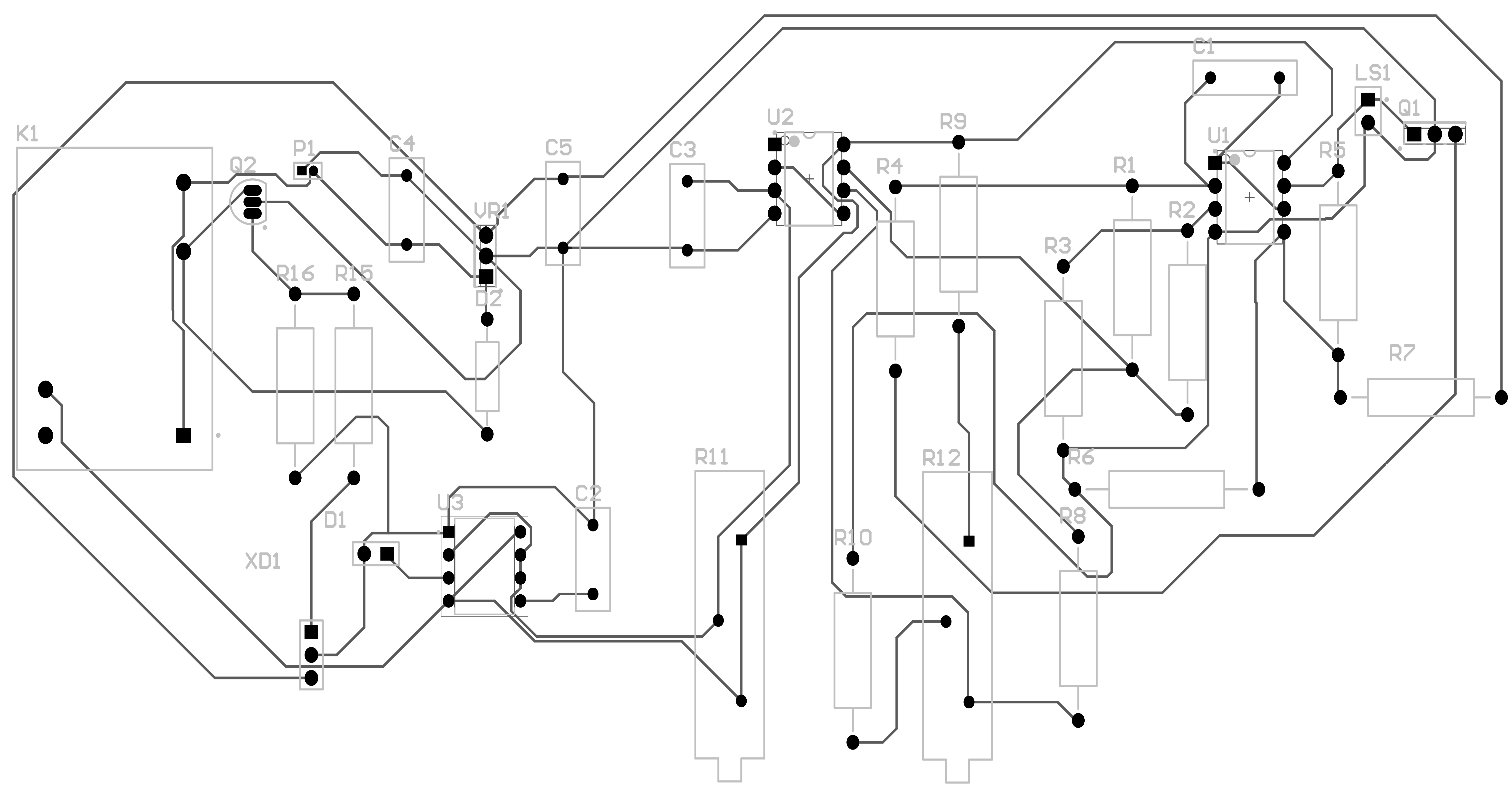
Download the plans from paleotronic.com/pumpkin.zip
PARTS
|
D1 |
Red LED |
|
D2 |
LL46 |
|
K1 |
6V relay |
|
Q1 |
MOSFET FDN8601 |
|
Q2 |
SL100 |
|
R1 |
100K |
|
R2 |
50K |
|
R3 |
50K |
|
R4 |
50K |
|
R5 |
100K |
|
R6 |
100K |
|
R7 |
100K |
|
R8 |
100K |
|
R9 |
3.3K |
|
R10 |
4.3K |
|
R11 |
Tap resistor 1M |
|
R12 |
Tap resistor 1K |
|
R15 |
100K |
|
R16 |
15K |
|
Speaker |
4W 3” |
|
C1 |
10 pF |
|
C2 |
0.01uF |
|
C3 |
0.1 uF |
|
C4 |
0.33 uF |
|
C5 |
0.1 uF |
|
VR1 |
7805 regulator |
|
U1,U2 |
LMC662 |
|
XD1 |
AMN31112 |
|
U3 |
NE555 |
Be the first to comment