
Cathode-ray tubes weren’t just useful for radar – all sorts of aircraft indicators were displayed with them.
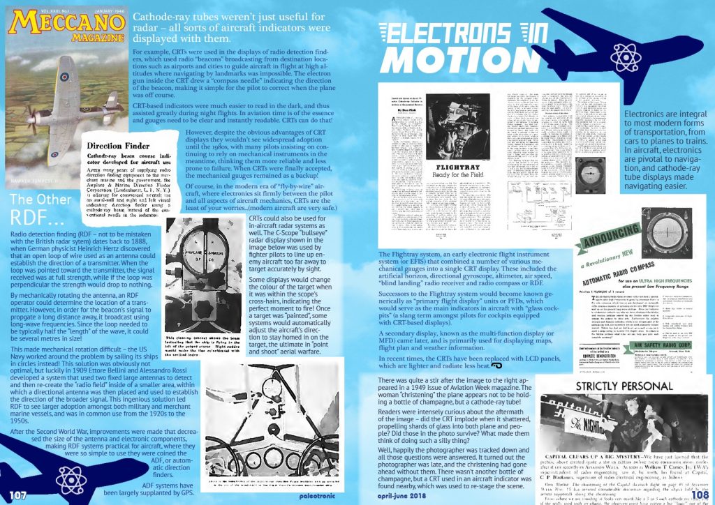
 For example, CRTs were used in the displays of radio detection finders, which used radio “beacons” broadcasting from destination locations such as airports and cities to guide aircraft in flight at high altitudes where navigating by landmarks was impossible. The electron gun inside the CRT drew a “compass needle” indicating the direction of the beacon, making it simple for the pilot to correct when the plane was off course.
CRT-based indicators were much easier to read in the dark, and thus assisted greatly during night flights. In aviation time is of the essence and gauges need to be clear and instantly readable. CRTs can do that!
However, despite the obvious advantages of CRT displays they wouldn’t see widespread adoption until the 1980s, with many pilots insisting on continuing to rely on mechanical instruments in the meantime, thinking them more reliable and less prone to failure. When CRTs were finally accepted, the mechanical gauges remained as a backup!
Of course, in the modern era of “fly-by-wire” aircraft, where electronics sit firmly between the pilot and all aspects of aircraft mechanics, CRTs are the least of your worries…(modern aircraft are very safe.)
 The Other RDF…
Radio detection finding (RDF – not to be mistaken with the British radar system) dates back to 1888, when German physicist Heinrich Hertz discovered that an open loop of wire used as an antenna could establish the direction of a transmitter. When the loop was pointed toward the transmitter, the signal received was at full strength, while if the loop was perpendicular the strength would drop to nothing.
By mechanically rotating the antenna, an RDF operator could determine the location of a transmitter. However, in order for the beacon’s signal to propagate a long distance away, it broadcast using long-wave frequencies. Since the loop needed to be typically half the “length” of the wave, it could be several metres in size!
This made mechanical rotation difficult – the US Navy worked around the problem by sailing its ships in circles instead! This solution was obviously not optimal, but luckily in 1909 Ettore Bellini and Alessandro Rossi developed a system that used two fixed large antennas to detect and then re-create the “radio field” inside of a smaller area, within which a directional antenna was then placed and used to establish the direction of the broader signal. This ingenious solution led RDF to see larger adoption amongst both military and merchant marine vessels, and was in common use from the 1920s to the 1950s.
After the Second World War, improvements were made that decreased the size of the antenna and electronic components, making RDF systems practical for aircraft, where they were so simple to use they were coined the ADF, or automatic direction finders. ADF systems have been largely supplanted by GPS.
 CRTs could also be used for in-aircraft radar systems as well. The C-Scope “bullseye” radar display shown in the image to the right was used by fighter pilots to line up enemy aircraft too far away to target accurately by sight.
Some displays would change the colour of the target when it was within the scope’s cross-hairs, indicating the perfect moment to fire! Once a target was “painted”, some systems would automatically adjust the aircraft’s direction to stay homed in on the target, the ultimate in “point and shoot” aerial warfare.
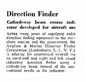
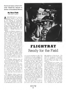 The Flightray system, an early electronic flight instrument system (or EFIS) that combined a number of various mechanical gauges into a single CRT display. These included the artificial horizon, directional gyroscope, altimeter, air speed, “blind landing” radio receiver and radio compass or RDF.
Successors to the Flightray system would become known generically as “primary flight display” units or PFDs, which would serve as the main indicators in aircraft with “glass cockpits” (a slang term amongst pilots for cockpits equipped with CRT-based displays).
A secondary display, known as the multi-function display (or MFD) came later, and is primarily used for displaying maps, flight plan and weather information.
In recent times, the CRTs have been replaced with LCD panels, which are lighter and radiate less heat.
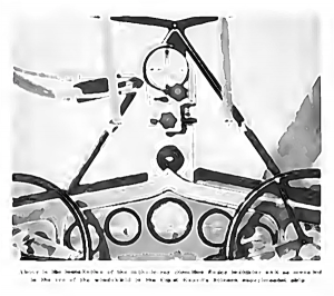
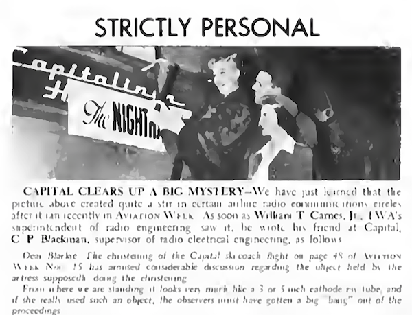 There was quite a stir after the image to the right appeared in a 1949 issue of Aviation Week magazine. The woman “christening” the plane appears not to be holding a bottle of champagne, but a cathode-ray tube!
Readers were intensely curious about the aftermath of the image – did the CRT implode when it shattered, propelling shards of glass into both plane and people? Did those in the photo survive? What made them think of doing such a silly thing?
Well, happily the photographer was tracked down and all those questions were answered. It turned out the photographer was late, and the christening had gone ahead without them. There wasn’t another bottle of champagne, but a CRT used in an aircraft indicator was found nearby, which was used to re-stage the scene.
Be the first to comment