
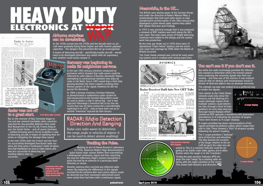
RADAR: RAdio Detection / Direction And Ranging
Radar uses radio waves to determine the range, angle or velocity of objects. It can be used to detect almost anything!
Airborne surprises can be devastating.
As the 1920s turned into the 1930s and the decade wore on, aircraft were gradually flying faster, higher and with heavier payload capacities – the dangers that presented did not go unrecognised.
A means of detecting aircraft – specifically, hostile aircraft – would need to be developed otherwise any nation with air supremacy over another could easily conquer it.
Germany was beginning to make its neighbours nervous.
In the late 19th century, scientists conducted experiments which showed that radio waves could be reflected by solid objects. A Russian, Alexander Popov, attempting to communicate between two ships by radio in the Baltic Sea in 1897, noted that a third ship passing between the them created a striking interference pattern in the signal. However, he did not ursue his discovery.
In 1904 a German inventor, Christian Hülsmeyer, demonstrated a rudimentary radar system he had constructed to the German Navy, which could be used to detect a ship in dense fog – but it was rejected! Hülsmeyer’s invention fell so far into obscurity that two US Navy researchers coincidentally replicated it in 1922 – only to have their not-so-inventive “invention” rejected by their bosses.
 Radar was not off to a great start.
But as the monster of Nazi Germany began to rise and war seemed inevitable, other countries searched for any possible defenses they could find. Researchers in the US, UK, France, Italy, Japan, the Soviet Union – and, of course, Germany – worked furiously and in secret to perfect a way of detecting aircraft, in hopes of repelling their enemies or mitigating the damage they caused.
In the mid-1930s, both the French and the Soviets successfully developed functional radar systems, but they used a “continuous” mode of operation that blanketed an area in radio waves and was less successful in detecting and tracking objects than its successor.
Tracking the Pulse.
 Working at the US Naval Research Laboratory in 1934, American Robert Page demonstrated a pulse-based radar system. Rather than transmitting a widespread continuous signal and then searching the area for reflections, Page’s system transmitted a pulse focused by an antenna in a particular, fixed direction, or vector.
Another antenna then received any reflected radio waves. By analyzing the differences in the signals received by the antenna after each pulse, objects could be detected and their movement determined much more easily than had been with a continuous signal.
 Meanwhile, in the UK…
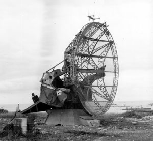
The British were keenly aware of the German threat, and under the direction of Robert Watson-Watt, a meteorologist who had used radio waves to map thunderstorm activity earlier in the 20th century, they developed a pulse-based radar system they called RDF (Radio Direction and Finding).
In 1935 it was practical enough that it was proposed a network of RDF stations was built along the UK’s east coast. Two years later, arrays of height-detecting antennas were added to the design, and the system went into production.
By the time war broke out in 1939, there were 21 operational “Chain Home” stations, and the entire east coast had coverage by 1940, when the Battle of Britain occurred.
The Chain Home network was critical for early-warning systems and is credited with saving many lives.
You can’t see it if you don’t see it.
But while the radio technology provided the information needed to determine where the enemy’s planes were, analysing the returning signals was time consuming – and time was of the essence. It was realised early on that an obvious and instantaneous visual indicator of detected objects was an absolute necessity.
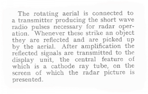
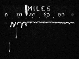
The cathode-ray tube was looked to as a preferred way to render the signals. Each station in the Chain Home network could only sense the distance, not the bearing of a target (although reports from multiple stations could determ- ine that, through a form of triangulation.) As such, they used oscilloscope-based displays which showed an RDF operator a waveform, with downward disturbances in it indicating the location of targets.
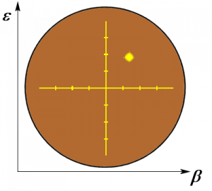
These were known as “A-scope” displays. B-scopes provided top-down representations of the signals provided by airborne radars, which swept from side to side. These showed a “slice” of airspace usually following the plane’s heading. The C-scope provided a “bullseye” view of direction and elevation. The blip showed the location of the target relative to the aircraft (or gun) the radar was att ached to. This is a common indicator used for targeting in air battle-style video games, and it often flashes when the target is in the “crosshairs”.
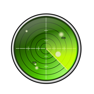
Finally, the plan position indicator (PPI) displays the area “swept” by a rotating radar antenna, with the radar’s position at the centre. This shows both distance and direction.
Be the first to comment