

In today’s world of plug-and-play peripheral devices, it is difficult to understand the fundamentals of what is happening at the lower levels. How does the computer connect to the device? How does it communicate with the device? How does the software make the device do its magic?
My name is Eric Rangell and I was a teenager in the 1980s. My first computer was an Apple //e in 1983. Before my family got a computer, I learned Basic programming from my brother’s college textbook and practiced writing programs on paper for a year before the Apple found a home in my brother’s room. With the limited computer time I had, I practiced coding, debugging, and refining my programs until they did what I wanted. The Apple ][ series of computers was designed so that owners could learn everything about how their machines worked if they took the time to study the available documentation and experiment with the machine. Today, early Apple computers can help young people grasp the fundamentals of how a computer works, and that will help them as they progress in their studies and careers.
In this article I will walk through a simple project that can be built using an Apple ][ series computer that has an internal Game I/O socket. It uses one of the Annunciator digital outputs to send MIDI data to a MIDI instrument. The process of building it and persisting through any problems you encounter will give you a sense of mastery and enjoyment, give you a tool to express your creativity, and challenge you to continue tinkering with the project as you learn more advanced computer science concepts. Parents and teachers are encouraged to learn how to build this project and help children work through it as they build an electronic device, write simple programs in Basic to control the device, and imagine additional applications that can use the device.
MIDI can play notes and music on keyboard synthesizers, as well as send commands to modules which control music playback, drum patterns, and even lighting. MIDI uses a very simple communication protocol to send binary messages to instruments. There really is nothing magical about it – the computer is just sending bytes which represent commands such as “Play a middle C”, “Stop playing the middle C”, “Change the instrument sound to Violin”, “Change the volume”. The objective of this project is for the student to understand how the computer varies voltage levels on an output port using specific timings according to a protocol that the musical instrument receiving the data understands. By building the interface from scratch, the student knows that the data is traveling on wires that they connected, and controlled by software that they wrote, using a driver program that is conceptually easy to understand.
Before you start building the interface, read this entire article and gather the parts you need. Many modern musical instruments have USB interfaces for MIDI. Look for older synthesizer keyboards with the round 5 pin DIN MIDI sockets, or USB MIDI interfaces that have the round connectors. You may need a MIDI coupler in order to connect a MIDI cable to one of those interfaces.
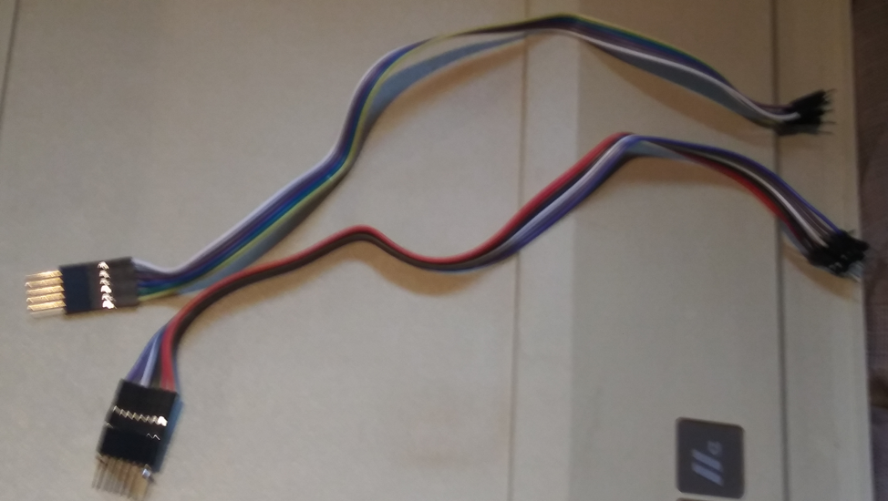
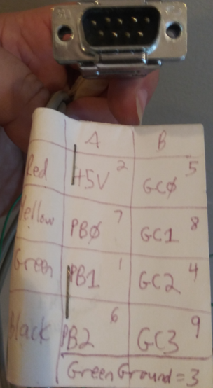
 Since this project is going to be built on an Apple ][ game I/O socket, the first task is to build a cable that makes the socket pins more accessible outside the computer. The best connection is a 16 pin to 16 pin cable where one end plugs into the socket and the other end plugs into a breadboard. If you cannot obtain this cable, you can make your own using ribbon cable with Male to Male pin connectors. If this MIDI interface is the only project you want to build on the Game I/O socket, there are only 3 pins that need to be routed externally. On an Apple //e or //gs, 2 of those pins (+5V and GND) can come from the 9 pin Game connector on the back panel of the computer using a DE-9 connector.
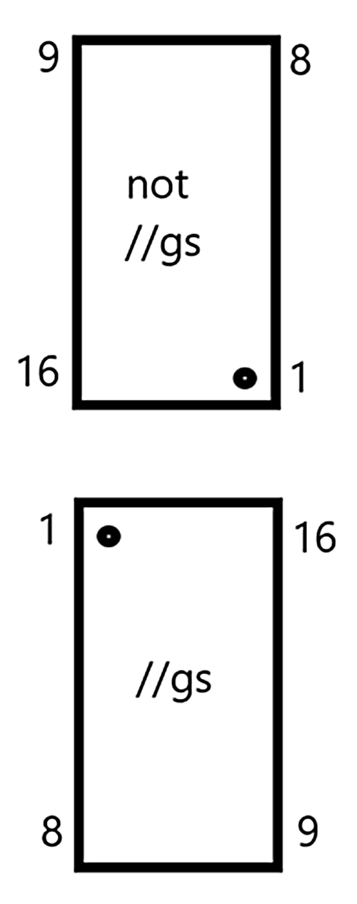
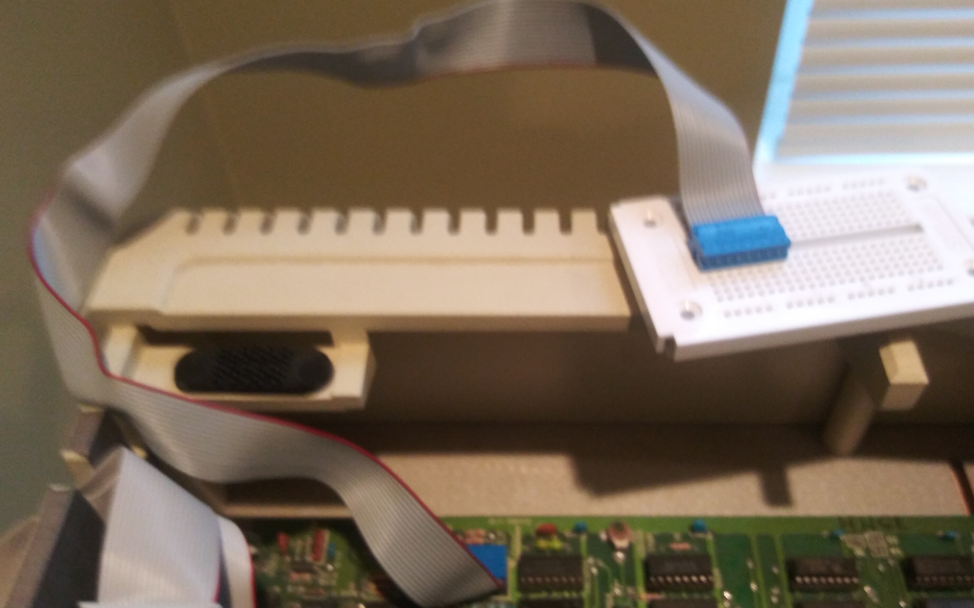
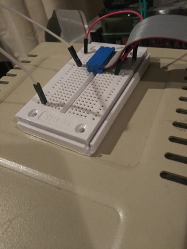
The following pictures illustrate various options for connecting the game socket to a breadboard. Keep track of which pins on the external connector correspond to which pins on the internal connector. On the Apple //gs, pin 1 is in the upper left corner of the socket. For all other Apples, pin 1 is in the lower right corner of the socket. Pins are numbered from pin 1 to pin 8, then pin 9 is on the opposite side of pin 8, then pins 9-16 are numbered using the remaining pins.

Testing your wiring
Before you proceed any further, you want to make sure all wires are properly connected and that the signals from the Apple are reaching the breadboard. While there are only 3 pins needed to build the MIDI interface project, take the time to test the additional signals available on the Internal Game I/O socket. All pin numbers below refer to pin numbers on the Internal Game I/O socket.
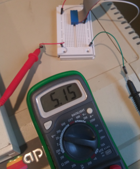
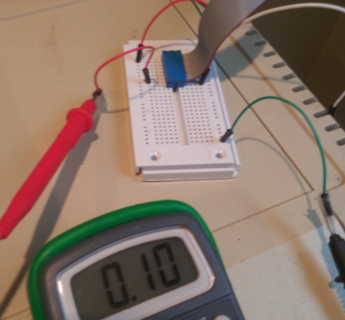
1. Test the voltage between +5V (pin 1) and GND (pin 8). Use a multimeter to verify that the voltage level coming to the breadboard is at least +5 volts. The red wire connects pin 1 to the side holes for Power and the green wire connects pin 8 to side holes for Ground. Connect the probes of the multimeter to the Power and Ground of the breadboard, and set the dial to measure voltage.
2. Test the digital logic from the Annunciator outputs. Each of the 4 Annunciator outputs is controlled by a pair of soft-switches which are mapped to memory locations. One of each pair sends a digital HIGH signal to the output, and the other soft-swich of the pair sends a digital LOW signal.
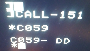
 To test the HIGH signal for Annunciator #0 (pin 15) go into the Apple Monitor by typing CALL -151 from Basic, and enter the hex address: C059, as shown below. The Apple will return a value for that memory location, which you can ignore. Now you can test to verify that Pin 15 has a HIGH signal.
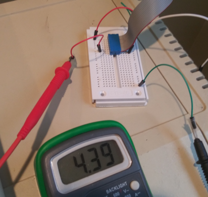
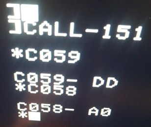 While the multimeter is connected, enter the hex address: C058 in the Apple Monitor. The voltage should drop to a very low value.
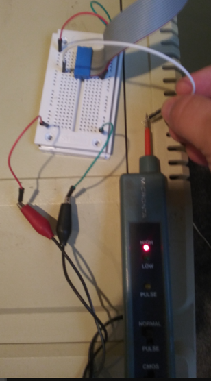

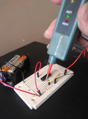
You can also test the logic of the Annunciators using a Digital Logic Probe, as shown left. Connect the probe terminals to the +5V and GND signals on the breadboard, then touch the tip of the probe to the Annunciator pin. The photos below show how the Digital Logic Probe responds when it detects logical HIGH and logical LOW voltages on Annunciator 0.
Inverters and Buffers
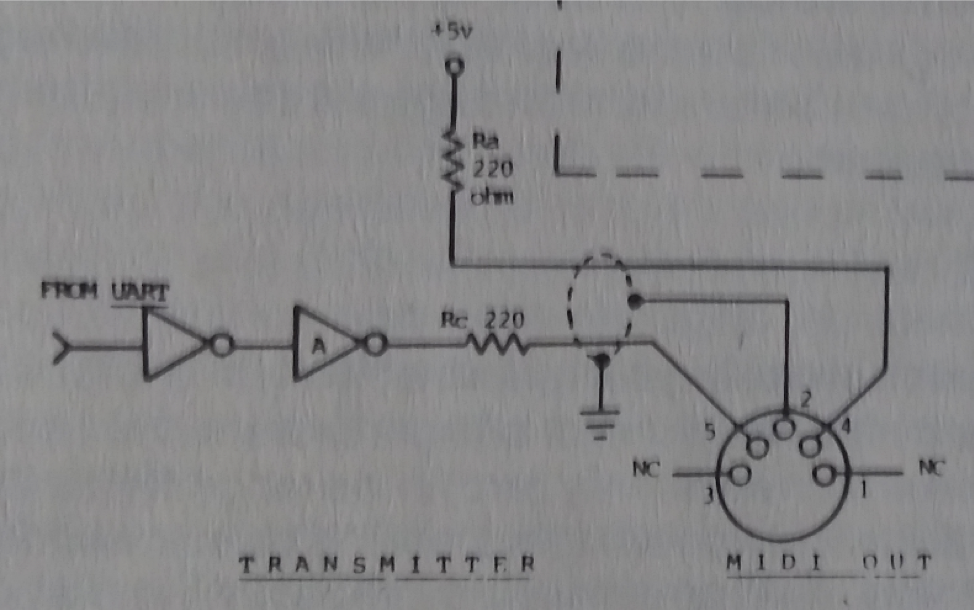
The MIDI specification defines the MIDI OUT Circuit as follows:
The signal from the transmitting device (labeled UART in the diagram below-left) passes through 2 inverters, then a 220 Ohm resistor, and is sent to Pin 5 on the circular 5 pin DIN connector labelled MIDI OUT. The +5V signal is sent through a 220 Ohm resistor to Pin 4 of the MIDI OUT connector. Pin 2 is connected to Ground, and the shield of the MIDI cable. Pins 1 and 3 are not connected. Polarity matters because a MIDI cable will connect your MIDI OUT port to the MIDI IN port of a musical instrument. The signals sent on your MIDI OUT port need to drive a phototransistor inside an opto-isolator in the MIDI IN circuit. When the signal from the UART is negative, the current loop is completed and the opto-isolator receives the signal. Communication is established by following a timing protocol for flipping the signals to represent the bits and bytes of MIDI messages. In this project we will control the timing of the messages with the Apple’s 6502 timing, to illustrate that there is nothing magical going on – if we get the timing right and follow the protocol, we will successfully communicate with a MIDI instrument.
Inverters change the input signal from HIGH to LOW, or LOW to HIGH. So, two inverters will leave the input signal unchanged. The two inverters form a buffer, which ensures that the signal does not get degraded if voltage fluctuates due to additional loads on the circuit. While it may be possible to drive the signal directly from the Apple without using the buffers, that introduces an element of uncertainty that can make your device unreliable under certain conditions. So initially we will build the circuit with two inverters (following the MIDI spec), and then test modifying it to use only one inverter (by logically inverting all the signals sent by the driver software).
 Testing your chips
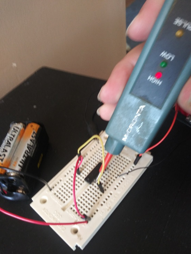
Use a logic probe to verify the outputs of each chip for each set of possible inputs. Use batteries or an electronics kit to test the chips before you use them in your project. The photos below show how one inverter of a 7404 Hex Inverter chip can be tested with a logic probe. The probe’s +5V and GND alligator clips are connected to the corresponding buses on the breadboard. The probe tip then is touched to the logic gate output. In the left photo, pin 1 (the yellow wire) is connected to +5V, so the logic probe reads LOW on pin 2. In the right photo, pin 1 is connected to GND, so the logic probe reads HIGH on pin 2. For both circuits, Pin 7 is connected to GND and pin 14 is connected to +5V.
There are several integrated circuit chips that can be used to build the buffer needed for this circuit:
4001: QUAD NOR – contains 4 NOR (NOT OR) gates
4011: QUAD NAND – contains 4 NAND (NOT AND) gates
7404: HEX INVERTER – contains 6 inverter circuits.
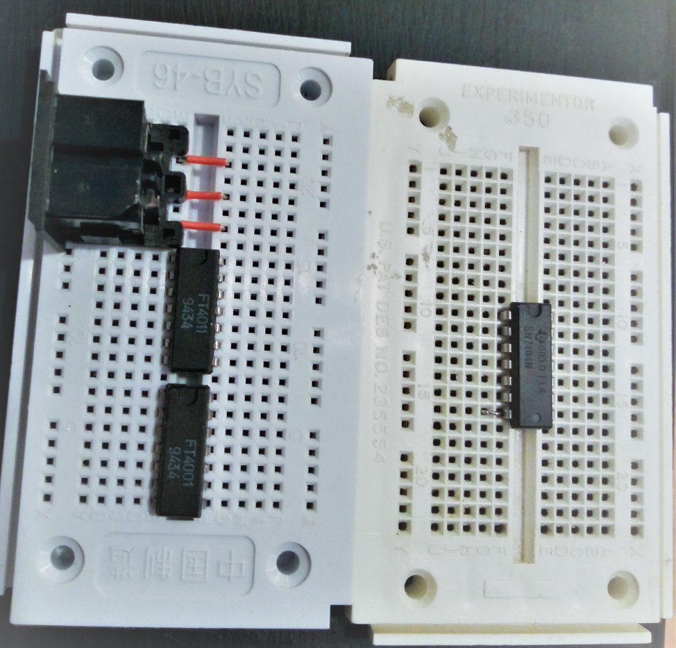
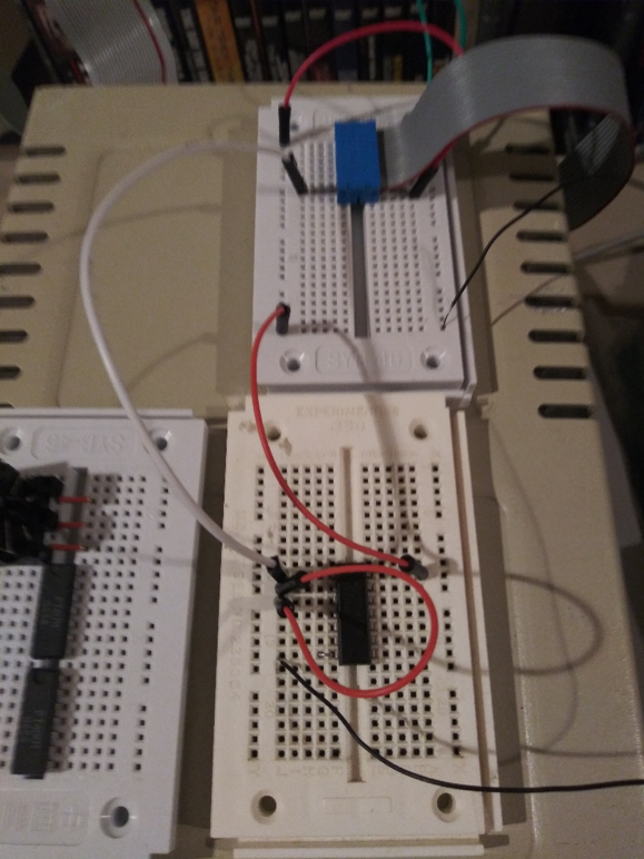
The two breadboards above show the three chips that may be used for this project. The left breadboard shows the 4011 chip on top and 4001 chip on the bottom. The right breadboard shows the 7404 chip. A MIDI socket from Sparkfun is shown at the top of the left breadboard, with 3 jumpers connecting the terminals for pins 2, 4, and 5 to the holes on the right. If you use the 4011 or 4001 chip, connect both inputs of each gate together to create inverters from the NAND or NOR gates. Search for pinouts and datasheets for each of these chips to learn how they should be connected in circuits.
Testing your chips
Use a logic probe to verify the outputs of each chip for each set of possible inputs. Use batteries or an electronics kit to test the chips before you use them in your project. The photos below show how one inverter of a 7404 Hex Inverter chip can be tested with a logic probe. The probe’s +5V and GND alligator clips are connected to the corresponding buses on the breadboard. The probe tip then is touched to the logic gate output. In the left photo, pin 1 (the yellow wire) is connected to +5V, so the logic probe reads LOW on pin 2. In the right photo, pin 1 is connected to GND, so the logic probe reads HIGH on pin 2. For both circuits, Pin 7 is connected to GND and pin 14 is connected to +5V.
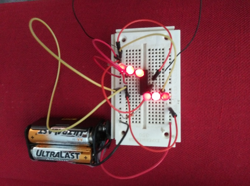
In the photo left, all 6 outputs of the 7404 chip are connected to LEDs, and all inputs to each of the 6 gates are connected to GND. All 6 LEDs light up because all outputs are HIGH. The TTL logic in the chip amplifies the current and provides +5V on each output which drives each LED. A buffer circuit can be made with 2 inverters by connecting the output of one inverter to the input of the other. Note that for some logic chips, all unused inputs must be connected to GND for the circuit to work.
MIDI Output Circuit Assembly
The following diagrams show how you would connect the Apple Game I/O connector to a 7404 Hex Inverter chip. Make sure power to your Apple is OFF while you are making these connections.
1. Apple Pin 1 (+5V), on bottom right of blue connector goes to +5V bus on breadboard, and to pin 14 of the 7404 chip (upper right pin – red wire).
2. Apple Pin 8 (GND) on top right of blue connector goes to GND bus on breadboard, and to pin 7 of the 7404 chip (lower left pin – black wire).
 3. Apple Pin 15 (AN0) on the pin above the lowest pin on the lower left of the blue connector goes to Pin 1 of the 7404 chip (Inverter IN, upper left pin, white wire).
4. Pin 2 of the 7404 chip (Inverter OUT) is connected to Pin 3 (Inverter IN), red wire.
5. Connect a 220 ohm resistor to Pin 4 (Inverter OUT) of the 7404 Inverter, then connect the other end of the resistor to Pin 5 of the MIDI socket (Yellow wire). The holes of the MIDI socket are on the bottom, so the pins shown left to right in the photo below are 5, 2, 4.
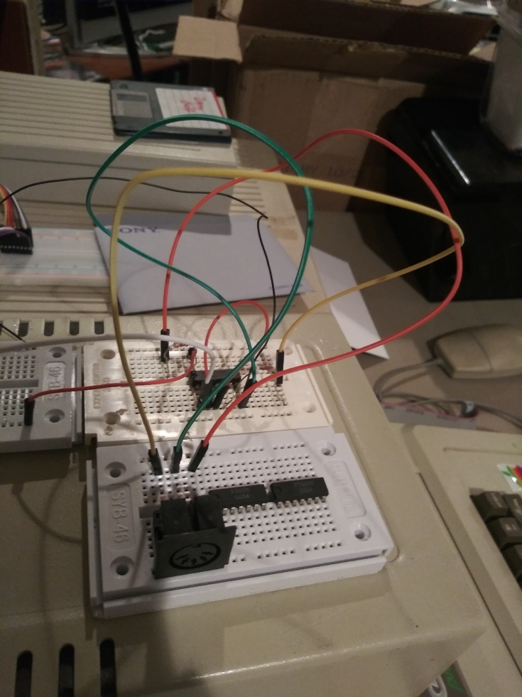
6. Connect a 220 ohm resistor to Pin 14 of the 7404 Inverter (+5V). Then connect the other end of the resistor to Pin 4 of the MIDI socket (Red wire).
7. Connect Pin 2 of the MIDI socket to Pin 7 of the 7404 Inverter (GND).
8. Connect a MIDI cable from the MIDI socket to your MIDI instrument. The MIDI instrument needs to have a round 5 Pin DIN port labelled MIDI IN (or “to MIDI OUT”).
Testing your MIDI Interface
You have built the hardware for the interface and connected it to your Apple. How will the Apple communicate with the interface? It needs a driver program to control the electronics of the interface. For this interface, the driver will send HIGH and LOW signals from the Annunciator output at precise times which will be interpreted by your MIDI instrument as commands. A communication protocol is needed – an agreement of what signals will be sent when, how they should be interpreted, and how the musical instrument should behave when specific commands are received. This protocol is documented in the MIDI specification, and many other resources available online.
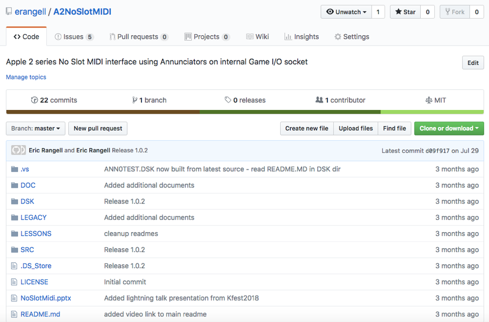
Where will the driver software come from? Apple ][ computers used floppy disks to load software. If your Apple has a 5.25 inch floppy disk drive, you can create a disk from a disk image file using software such as ADT Pro. Or if you have a hardware device such as the Floppy Emu, you can copy a disk image file to a Micro SD card and load the disk image from the device. The disk image containing the driver software for this MIDI interface can be downloaded from Github at:
https://github.com/erangell/A2NoSlotMIDI
Click the “Clone or Download” button and download the whole project as a ZIP file.
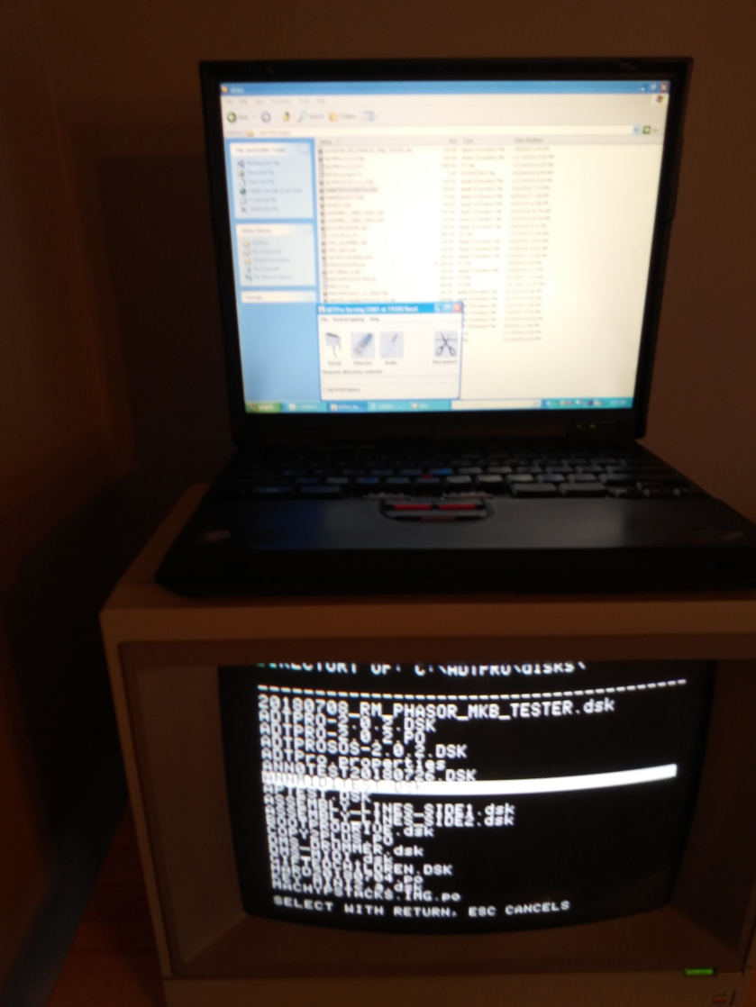 The disk image containing the driver software is located in the DSK subdirectory and is named ANN0TEST.DSK. You will need to either create a floppy disk from this disk image or copy the file to an SD card for a hardware floppy disk emulator device. The photo below shows how a floppy disk image file on a Windows laptop (in C:\ADTPRO\DISKS) can be copied to an Apple 5.25 floppy disk using ADT Pro over a Serial cable connected to an Apple Super Serial Card. For more information, please visit:
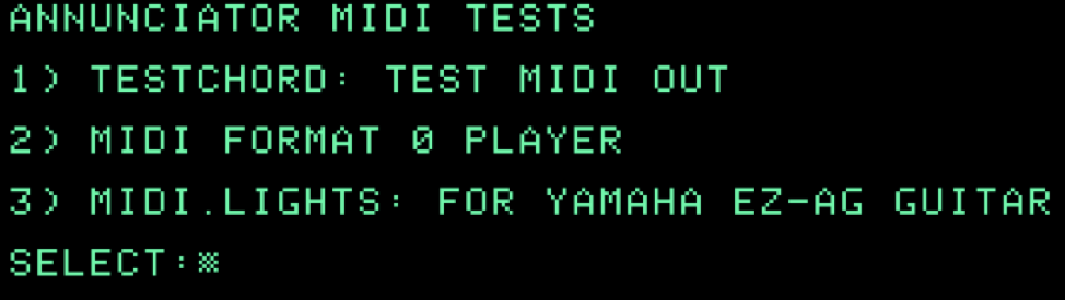
When you boot the floppy disk on the Apple where you connected your MIDI interface you will see the menu above.
Select option 1 to test playing a chord on your MIDI instrument.
If you hear the chord play, give yourself a big pat on the back! You built an electronic device that successfully connected a vintage Apple computer to an electronic musical instrument using MIDI!
If you did not hear the chord play, take a break and plan your troubleshooting strategy.
If you are using an Apple IIgs it needs to be running at Normal speed (1Mhz). This is done in the Control Panel.
Otherwise, look at your electronic connections and see if there are any incorrectly connected wires, incomplete circuits, or shorts. Take the time to test to see if enough current is getting to the logic chip. Sometimes you have to step back, undo some work, and even start over. Learn to work through frustration, make observations, and use the scientific method to deduce what is happening.
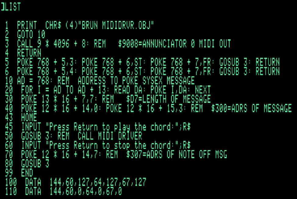
When you have your interface working, take a look at the BASIC program that played the chord.
Line 1 executes the binary file named MIDIDRVR.OBJ. This file contains the Machine Language instructions that control the switching of the Annunciator output using specific timings based on the MIDI Wire protocol specification. Line 2 then skips over the subroutines on lines 3, 5, and 6.
Line 3 calls a subroutine in the driver which sends MIDI data out of the interface.
Lines 5 and 6 can be ignored – they are left over from another program that controls LEDs on a MIDI guitar fretboard. You can also ignore the comment on line 10 – it is the guitar program uses MIDI SysEx messages.
Lines 10 and 20 poke the MIDI data to be sent into a free memory block. There are 14 bytes of data on lines 100 and 110 that will be stored. This data contains MIDI messages that control playing of notes on the instrument.
Line 30 tells the driver that 7 bytes (the data on line 100) should be sent when we call the driver. The number 7 is poked at memory address $D7 (13*16+7).
Line 40 tells the driver where in memory it should find the 7 bytes we want to send. The address 768 = 3 * 256. In hexadecimal, it is written as $0300. The low byte of the address ($00) is poked first at hex address $CE (12*16+4), and the high byte ($03) is poked at $CF (12*16+15).
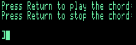
Lines 43-45 print a prompt message and wait for the user to press the Return key.
Line 50 calls the subroutine on line 3 to send the MIDI data to the driver. The chord then begins to play.
Line 60 prompts the user to press Return, and then waits for user input. The chord continues to play.
Line 70 changes the address of the MIDI message to $0307, so it now points to the data from line 110, which contains the MIDI instructions to stop each note of the chord.
Line 80 calls the subroutine on line 3 to send the MIDI data to the driver. The chord then stops playing.
Line 99 ends the program. Type RUN to run it again.
The data on line 100 is explained below:
144, 60, 127 = MIDI NOTE ON message, Note #60 = Middle C, 127 = maximum volume
64, 127 = MIDI NOTE ON message, Note #64 = E above Middle C, 127 = maximum volume.
Whenever a series of MIDI messages have the same command (ex: 144 = Note on), the command byte can be omitted. This is known as “Running Status”. The note number for E is 64 because on a piano keyboard the note E is 4 semitones above C. So if C is 60, C#=61, D = 62, D#=63, and E=64.
67, 127 = MIDI NOTE ON message, Note #67 = G above Middle C. If we start counting at E=64, then F=65, F#=66, and G=67.
The data on line 110 is explained below:
144, 60, 0 = MIDI NOTE ON message, Note #60 (middle C), 0 = minimum volume (no sound). When a NOTE ON message has a volume of 0, it is essentially a NOTE OFF message. (Note: There is a separate MIDI NOTE OFF message which can be used in place of this message, which will have the same effect).
64, 0 = turns off the E that was playing.
67, 0 = turns off the G that was playing.
Now it is your turn to experiment with this program and learn about MIDI as you go.
Try adding the following lines:
75 POKE 13*16+7, 3
82 INPUT “PRESS RETURN”;R$
84 POKE 13*16+7,2: POKE 12*16+14,10: GOSUB 3
86 INPUT “PRESS RETURN”;R$
88 POKE 12*16+14,12: GOSUB 3
RUN the program. What does it do now? Take notes of your observations and experiment with the code. Change the data to play different notes. How would you play the same notes one octave higher or lower? Have fun changing the program to play your favorite song. Try writing subroutines to play a sequence of notes and calling the subroutines several times.
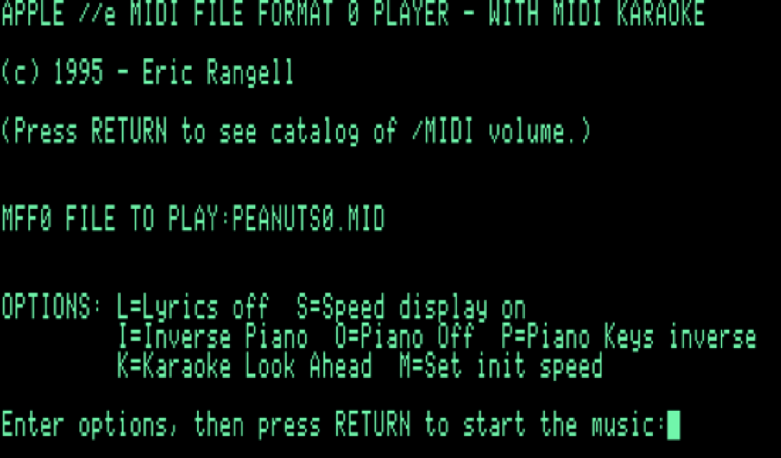
Also, try running the MIDI FORMAT 0 PLAYER PROGRAM (option 2 on the main menu). When prompted for the MFF0 file to play, enter
PEANUTS0.MID as shown below. Then press RETURN to play the music. Note: this program requires 80 columns and 128K of memory.
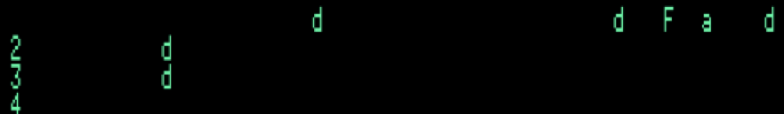
You will see the note names displayed on the 80 column screen as the music plays.
The following screenshot shows a D major chord being played. The uppercase F indicates an F# note.
This program is a combination of Applesoft and Machine Language code that uses the same driver program for the MIDI interface.
You now see how there is a separation of Application code from Driver code for the hardware. The Application code handles the loading of music data from the song file on disk, the timing of when the musical notes should be sent (based on the data in the file), and the display of the notes that are being played. The Driver handles all communication with the hardware.
The same principles are used in modern computer applications. When you install a peripheral on a modern computer, such as a printer, it needs a driver program in order for the computer to communicate with the hardware. The application software then needs to know how to communicate with the driver to make it perform high level tasks, such as printing a document.
This project shows you that there is no magic inside the computer – it is all electronic circuits following instructions using protocols to communicate with other electronic components. Everything happens very fast with precision timing, and you can see how an error anywhere in the process can make things appear not to work, but the computer is just following the exact instructions that it is given. Programmers need to anticipate all possible error conditions and make sure their code handles them properly. Sometimes problems occur due to unexpected sequences of events or timing issues.
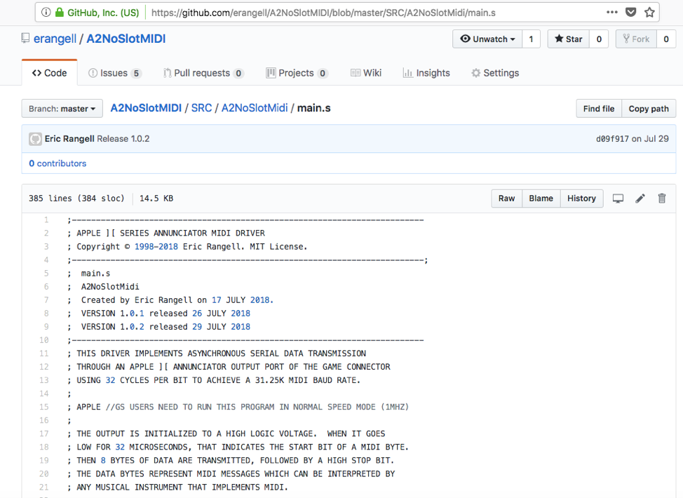
In future articles, we will look at the machine language driver code to understand how it communicates with the hardware, and explore advanced concepts such as using interrupts to improve the timing accuracy of music playback. If you understand assembly language and want to look at it yourself, go to the SRC directory on the Github site and look at the file: main.s in the A2NoSlotMidi subdirectory. Read the comments and try to understand how the program works. Then experiment with it. You have built your own MIDI interface and now have everything you need to build your own applications with it.
Welcome back to the exciting 1980’s world of vintage Apple ][ programming!

Be the first to comment