 So, it’s 1983 and you’ve saved up and bought yourself a shiny new computer with state-of-the-art graphics capabilities, and you’re ready to become a digital Picasso. But then you realise the only way you can ‘draw’ on your computer’s screen is either programmatically (either via BASIC or Logo) or through a graphics application, which offers either the keyboard or joystick as methods of input, neither of which gives you anywhere near the freedom required to draw what you want in a timely and non-frustrating fashion. What do you do?
Well, you could get a light pen.
What the heck is a ‘light pen’? Glad you asked!
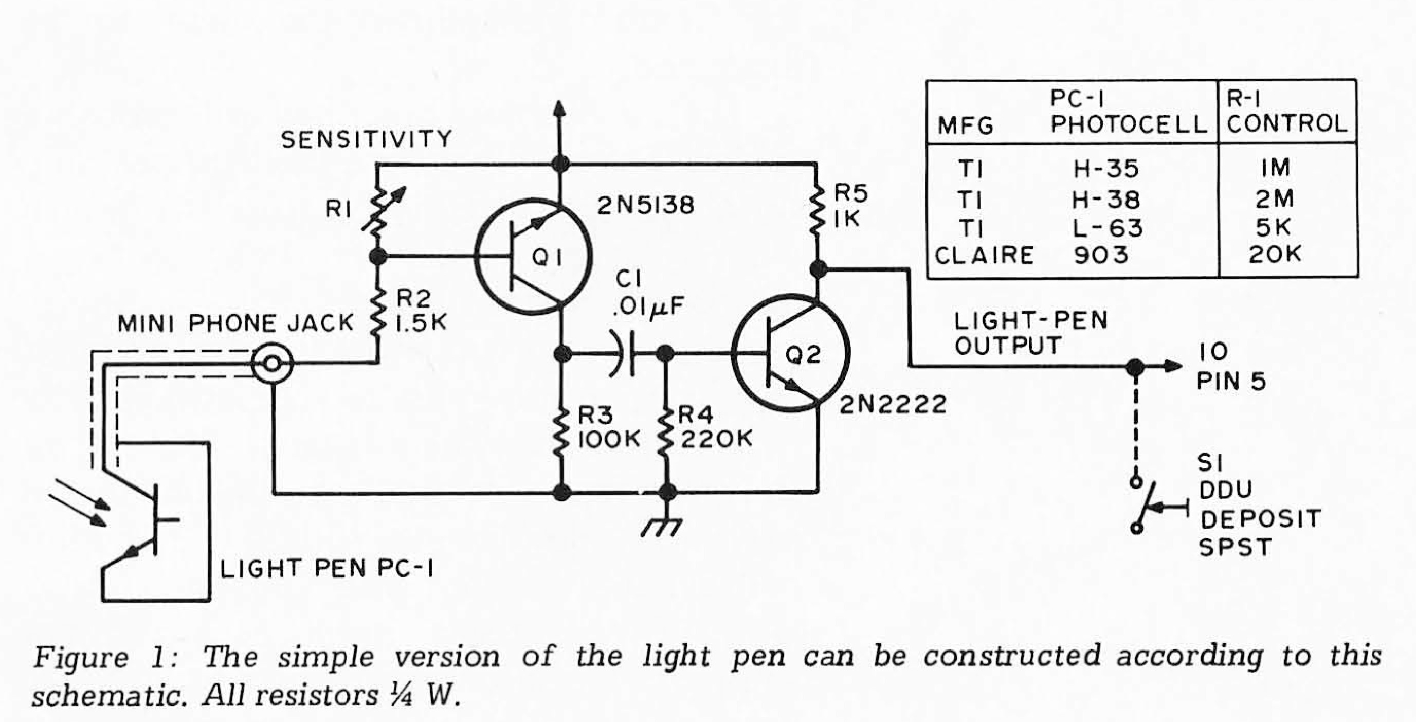
A light pen is an electronic device that senses when the electron gun inside of a cathode-ray tube (CRT)-based display sweeps past the location on the screen the light pen is pointing at. By calculating where the CRT is in its sweep relative to the top-left corner of the screen, the light pen can determine its location, and then it tells your computer software so it knows where to plot a pixel or activate a desired GUI control.
Actually, that’s not quite true – the light pen simply returns a voltage to the computer that increases or decreases relative to the amount of light that its photoelectric ‘eye’ is seeing. It’s up to the software inside the computer to decide at what level that voltage indicates the CRT gun is directly aimed at the light pen. And this is where we start running into trouble. Some CRTs are brighter than others. The contrast may make it easier or harder to determine just where the “bright spot” is – if the contrast is sharper it is easier to detect the pass of the electron gun where its bright but harder where it’s very dark. The ‘persistence’ of the phosphors on the interior of the screen can increase the area of the screen that will return the maximum voltage level as the electron gun sweeps past it, decreasing the accuracy of the pen. Different colours also have different brightness levels, which makes simple light pens much better suited to monochrome displays. If all you’re looking for is the ‘bright spot’, you’re in for a world of trouble.
 You can mitigate many of these issues by taking a more sophisticated approach. If you measure the rise and fall of the brightness of the pixel the light pen is pointing at over a few frames of video (and hence a few passes of the electron gun), you can calculate when the electron gun passes that pixel, no matter how bright or dark it is. But this requires more complicated circuitry or software. Which meant a more expensive computer, or a more expensive light pen.
If the light pen is doing the work then it can simply tell the computer when the spot it’s pointing at is at its brightest, assuming the screen doesn’t change while it’s figuring that out, at which point it will need to figure it out again. When it does, it just increases the voltage on a line, sending a 1.
 If the computer does the work, then it will be limited by the resolution of the data it can get from the light pen – on 8-bit computers connected via a joystick (really the paddle) port, this was usually limited to a single 8-bit number, that is, a number in the range 0 to 255.
This resolution could sometimes not be sufficient to detect the absolute peak of the luminance received, and the computer could calculate the position as too early, or too late, depending on if it relied on the start of the maximum input or the end of it. This could make the light pen’s reported position inaccurate, and while not necessarily a problem for simple applications or drawing at low resolutions, high-resolution drawing could be difficult. Red or reddish pixels could make this even worse, as red phosphors took longer to decay, exacerbating the issue. But when they worked properly they were cool!
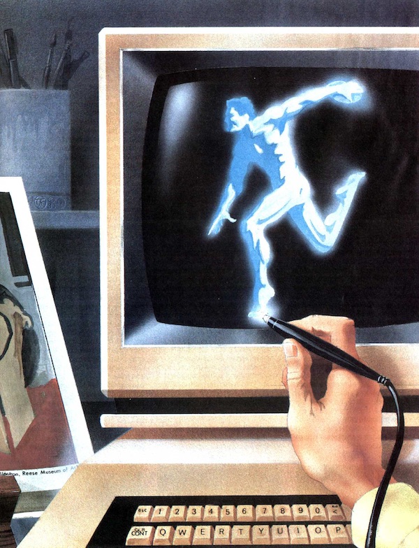 However, as cool as light pens could be, holding them was tedious and long-term use would result in “gorilla arm”, a condition caused by the arm muscles remaining tense for extended periods that makes the arm weak and fine motor control difficult – rendering the value of the light pen over any other pointing device largely moot.
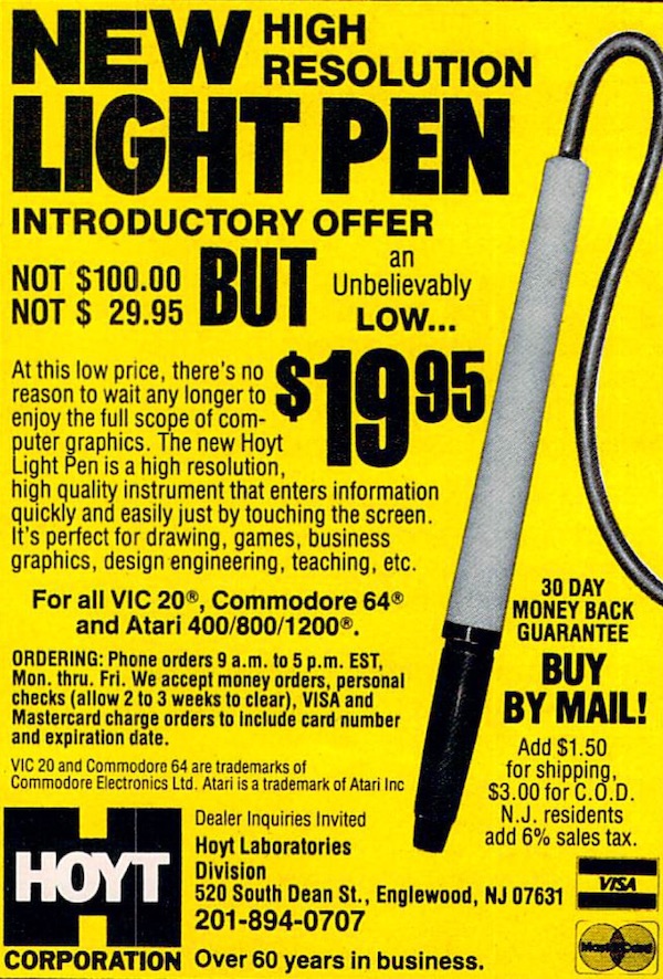
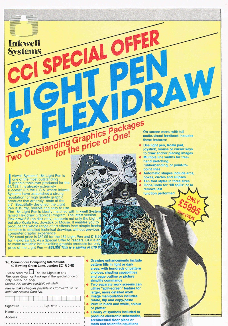
So, although your mileage could totally vary depending on your computer, the light pen you bought and the software you used, there was something futuristic about drawing directly on your computer screen, even if it wasn’t terribly practical, and people were happy to give it a go despite the mixed reviews, especially if it was cheap.
In consequence, for most people, the light pen was something they used once or twice and then threw in a drawer and forgot about. But there were plenty of people (suckers) to sell them to!
 As the resolution of graphics tablets improved, the number of creative or drafting professionals using even more sophisticated light pens decreased, and the market for light pens diminished into non-existence. Manufacturers stopped making them, advertising them or selling them. They were relegated to the past.
Eventually the end of the CRT monitor spelled the end of the light pen’s usefulness full-stop, its dependence on the technology behind the CRT making them entirely incompatible with LCD and LED displays.
These days, you can draw on your iPad, a significantly improved experience.
The pen-plotter was, in a way, the reverse of the light pen.
Rather than the user drawing on a screen, the computer drew on paper. However, instead of the raster-like back-and-forth of the dot-matrix printers, the plotter drew individual vectors, much like the turtle in the Logo programming language.
 Much like a Logo program, rather than the computer storing a user’s drawing as a flattened bitmap and modifying it as the user makes changes, the computer stores the vectors (or lines) that make up the user’s drawing as the user is drawing it, rendering it to the screen sequentially whenever the drawing is loaded or the screen needs to be re-drawn.
On 8-bit computers this was much slower than simply storing a flattened bitmap, but had the benefit that pen plotters could accurately replicate the drawing without any pixelisation. The drawing was sent to the pen plotter using ‘control languages’ that looked a lot like Logo turtle commands:
 In the example to the left, the printer is instructed to take the first pen out of its ‘stall’ (SP1), move to the top-left corner (location 0,0) of the paper (in landscape orientation) (PA = Plot Absolute), put the pen to paper (PD = Pen Down), draw a vertical line 1000 units relative down (PR = Plot Relative to current position), then lift the pen up (PU), move 1200 units to the right, put the pen down again, draw a vertical line up the paper 1000 units, lift the pen up again, and then return the pen back to its stall (SP).
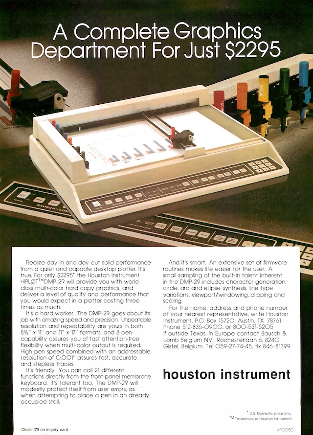
 The result is a page with two vertical lines. Note that each command ends with a semicolon, so that the printer knows the command has finished and it can process it. These printers didn’t have a lot of memory (neither RAM nor ROM) and so they had to be very economical with their programming languages! This particular plotting language was developed by Hewlett-Packard and was called HP-GL. Another language, from rival Houston Instruments, was called DMPL.
Computer users, however, didn’t usually need to program the printers directly. They could use BASIC ‘extensions’ (additional commands added to built-in BASIC interpreters by loading a binary program after the computer was turned on). These extensions allowed them to control the printer using commands such as PLOT, PEN and SCALE, the latter able to translate pixel co-ordinates into printer co-ordinates (the printer usually having a much larger ‘grid’ from which to work with, in an era when most screens were less than 200 pixels wide, if they could even display pixels at all.)
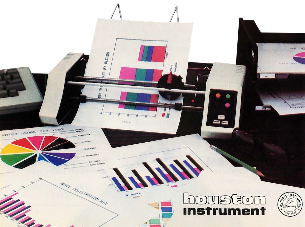
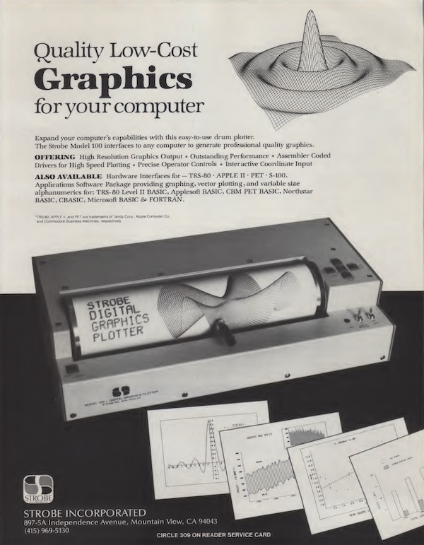
Plotters came in a few different designs. Early plotters wrapped the paper around a drum, and then moved the pen horizontally across the drum, rotating the drum in order to move vertically. Sometimes the paper had perforations, like ‘tractor feed’ paper for dot-matrix printers, although the model below appears to use electro-static charging to hold the paper in place. The model at the bottom of the page used friction rollers to keep the paper straight, and a roller behind to move it, while the plotter at the bottom of the opposite page used two tiny wheels, known as ‘grit wheels’ which created tiny indentations as the printer moved the sheet back and forth, ensuring the page remained straight.
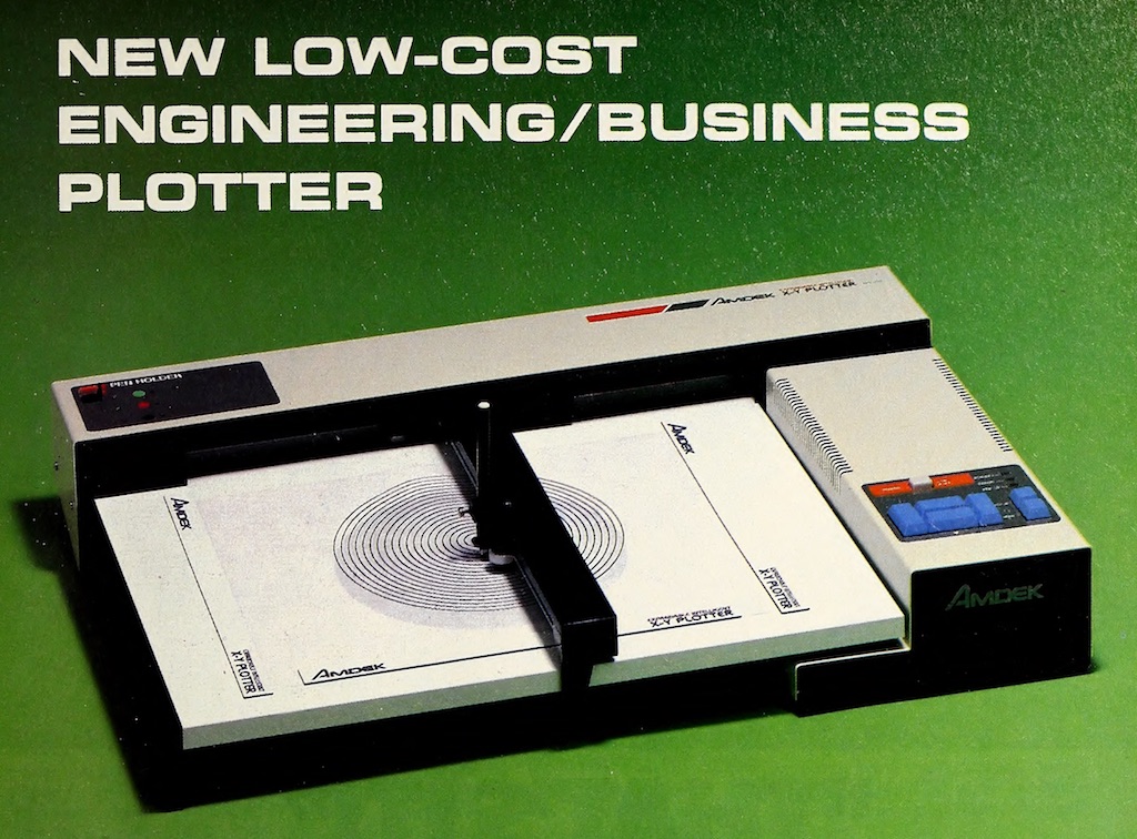
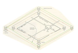
 However, the ‘flatbed’ plotter is the most recognisable style of pen-plotter. With a flatbed plotter, the paper remains stationary, and the pens are moved both vertically and horizontally by the means of two bars driven by pulleys and toothed belts or wires. Although it was the slowest of all the plotting methods (plotting was slow!), and pages had to be manually inserted and removed, users did not need to worry about the paper coming askew and ruining the drawing, or wrinkling or jamming.
Also, the flatbed plotter was much more suited to having multiple pen colours, with some featuring 8 different pens!
Be the first to comment