

The Apollo Guidance Computer (AGC) was a fascinating design for its time, and demonstrated many concepts that would take hold be used for many years to come.
 The 512Khz master signal (derived from a 2Mhz crystal clock) was divided down into a number of smaller timing signals that were used to trigger events at regular intervals, for example a 100Hz signal was used to update a real time clock, and an even lower frequency signal (every 1 and a half minutes) could be used to wake the computer when it was in a low power state.
The CPU had a multitude of registers, but the core registers were A (accumulator), Z (program counter), and Q (quotient but also used to store a return address from a call).
The instructions for the AGC used a 16 bit word, with 3 bits for the opcode, and 12 bits for the address value. This gave 8 basic instructions, and 3 additional instructions by use of a special call beforehand.
 For example: TC transferred control to a specified address. It stored the next instruction address in the Q register, so it could be used for subroutine calls. This was before processors used a stack to keep track of such things.
AD, SU, DV and MP implemented addition, subtraction, division and multiplication of the accumulator (A) register with a value specified by the address portion of the instruction. Other instructions were responsible manipulating data and registers.
Additionally, to provide further functionality, interacting with specific memory addresses could trigger other specific functions in the computer, almost acting as soft switches or virtual instructions.
In order to supplement the simple instruction set and to perform more complex tasks such as trigonometry, the AGC implemented a “virtual machine” that supported more complex instructions. These instructions could be intermixed with the real opcodes, and the assembler would make sure there was a smooth transition between these and the regular instructions. This is why one will see more than 11 instructions in the source code.
Looking at the code, for example, one will see a MXV instruction which is actually a matrix operation. This is an instruction that is implemented within the interpreter to multiply a matrix by a vector.
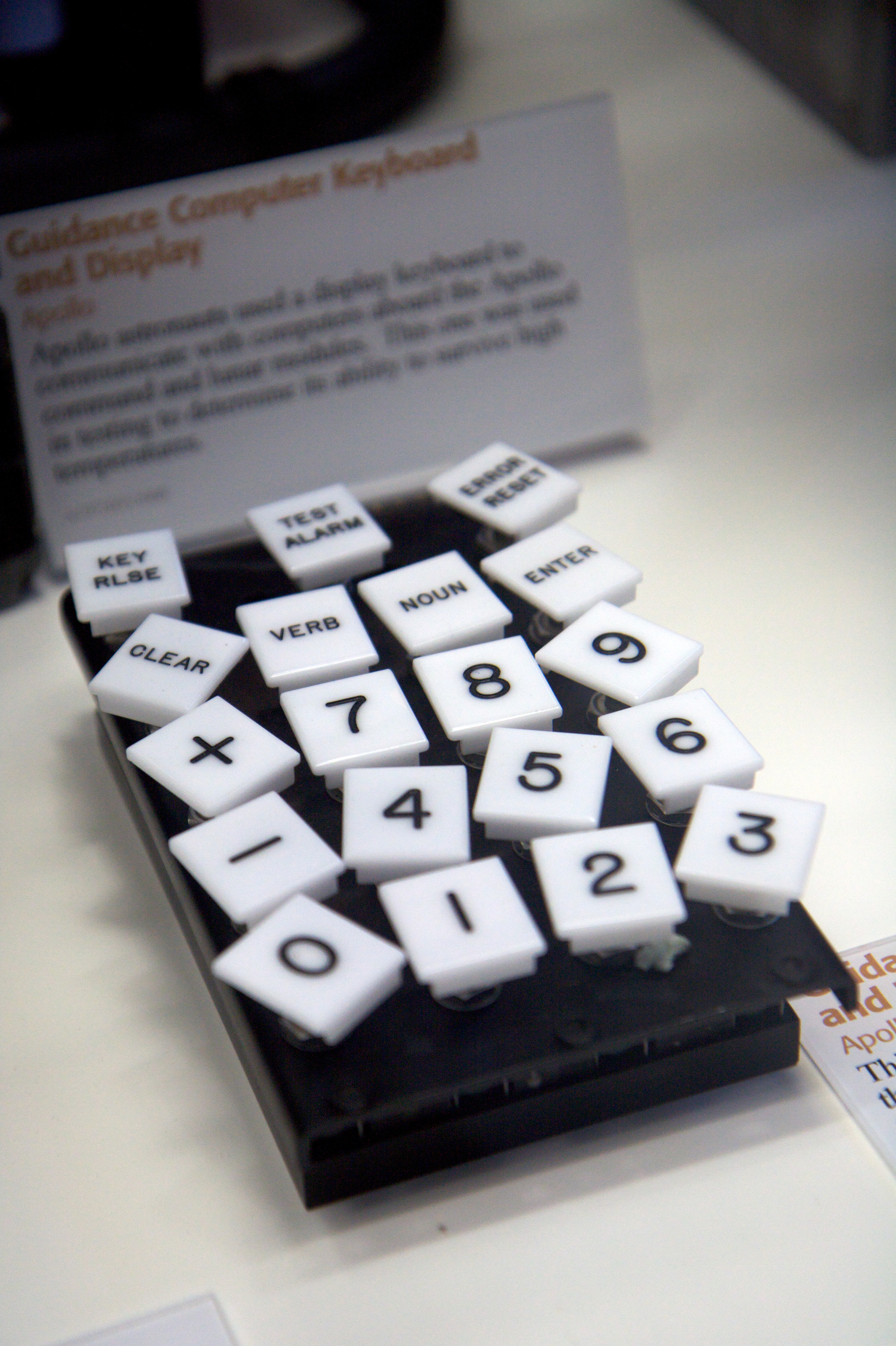
The system also supported interrupts. When an interrupt was triggered the CPU would save it’s current state, call the interrupt service routine, then resume where it left off previously. There were five types of interrupts in total. ERUPT was a critical one, that was triggered when an alarm was triggered so that the astronaut was alerted. DSRUPT was used to update the display data, KEYRUPT handled user input.
Another feature the system implemented was an element called the waitlist which could schedule and manage multiple short tasks, predominantly driven by timers. These tasks could reschedule themselves back onto the waitlist for further execution at a later interval. Longer running tasks generally were managed as jobs by another module called the executive.
These elements were impressive to me; it allowed a lot of different threads of execution to be tracked and maintained — and flying a spacecraft needs them! Many, many subsystems need to be managed and orchestrated in such a way, that critical tasks are executed in a timely fashion.
The amount of ingenuity and forethought that seems to have gone into the guidance computer – both into its engineering and its software remains impressive to this day. It is easy as a software engineer in the modern sense to forget that we stand on the shoulders of giants.

See the AGC code at https://github.com/chrislgarry/Apollo-11
Be the first to comment