
In the 1960s, television was something that was a passive occupation, you turn it on an it entertained you. The possibility that you might be able to create or manage what you saw on the television was science fiction.
The television system as it was designed was based on a phosphorescent dot traveling across the screen with a horizontal frequency of 15,734 Hz and a vertical frequency of 59.94 Hz (NTSC). This gave 525 lines in each field and a frame rate of 29.97 Hz.
This system was perfect if what you were doing was scanning an object (someone’s face) and then transmitting it to a television in another town. But what if you want to put the ball of a Pong game on the screen. You have to recreate the horizontal and vertical frequencies and synchronise those with your ball object. For example, if the ball was in the center of the screen you would have to have a jump the video signal every 33.3 mS (milliseconds) after the start of the frame.
So in order to play Pong you need a device that will create all the necessary synchronizing frequencies and move the paddles and dots around. There are two ways to do this analog and digital. The digital process is very easy in today’s technologies, Buy a PIC (Programmable Intelligent Computer) microcontroller and there are a number of small programs that will display a Pong game – all you have to do is make the controllers. The analog version is harder to do. There was a Pong game that was featured in Electronics Australia in May of 1976. It used some digital components yet it is analog in design.
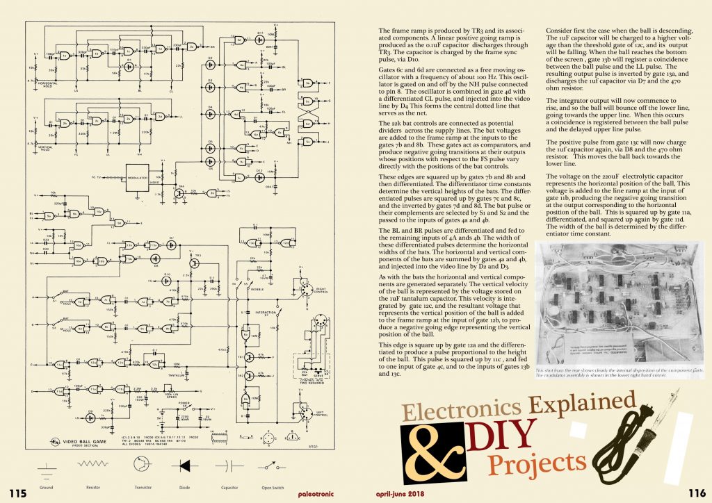
The circuit is designed on the 74C series CMOS logic quad NAND gates and 74C series NOR gates.
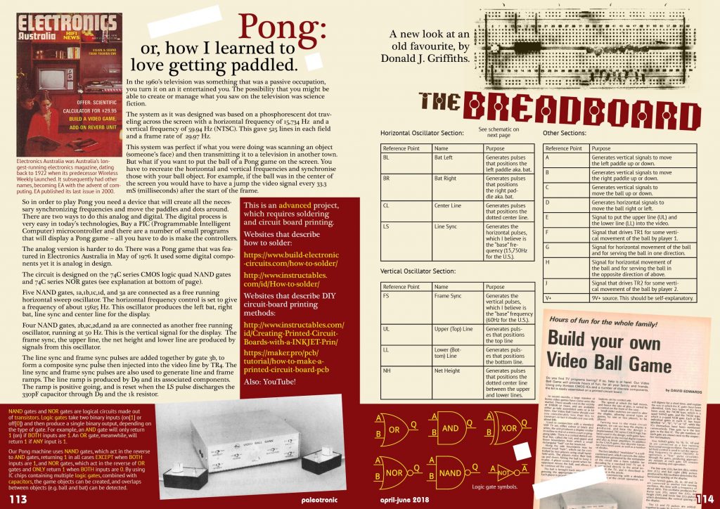
NAND gates and NOR gates are logical circuits made out of transistors. Logic gates take two binary inputs (on[1] or off[0]) and then produce a single binary output, depending on the type of gate. For example, an AND gate will only return 1 (on) if BOTH inputs are 1. An OR gate, meanwhile, will return 1 if ANY input is 1.
Our Pong machine uses NAND gates, which act in the reverse to AND gates, returning 1 in all cases EXCEPT when BOTH inputs are 1, and NOR gates, which act in the reverse of OR gates and ONLY return 1 when BOTH inputs are 0. By using IC chips containing multiple logic gates, combined with capacitors, the game objects can be created, and overlaps between objects (e.g. ball and bat) can be detected.
Five NAND gates, 1a,1b,1c,1d, and 3a are connected as a free running horizontal sweep oscillator. The horizontal frequency control is set to give a frequency of about 15625 Hz. This oscillator produces the left bat, right bat, line sync and center line for the display.
Four NAND gates, 2b,2c,2d,and 2a are connected as another free running oscillator, running at 50 Hz. This is the vertical signal for the display. The frame sync, the upper line, the net height and lower line are produced by signals from this oscillator.
The line sync and frame sync pulses are added together by gate 3b, to form a composite sync pulse then injected into the video line by TR4. The line sync and frame sync pulses are also used to generate line and frame ramps. The line ramp is produced by D9 and its associated components. The ramp is positive going, and is reset when the LS pulse discharges the 330pF capacitor through D9 and the 1k resistor.
The frame ramp is produced by TR3 and its associated components. A linear positive going ramp is produced as the 0.1uF capacitor discharges through TR3. The capacitor is charged by the frame sync pulse, via D10.
Gates 6c and 6d are connected as a free moving oscillator with a frequency of about 100 Hz. This oscillator is gated on and off by the NH pulse connected to pin 8. The oscillator is combined in gate 4d with a differentiated CL pulse, and injected into the video line by D4 This forms the central dotted line that serves as the net.
The 22k bat controls are connected as potential dividers across the supply lines. The bat voltages are added to the frame ramp at the inputs to the gates 7b and 8b. These gates act as comparators, and produce negative going transitions at their outputs whose positions with respect to the FS pulse vary directly with the positions of the bat controls.
These edges are squared up by gates 7b and 8b and then differentiated. The differentiator time constants determine the vertical heights of the bats. The differentiated pulses are squared up by gates 7c and 8c, and the inverted by gates 7d and 8d. The bat pulse or their complements are selected by S1 and S2 and the passed to the inputs of gates 4a and 4b.
The BL and BR pulses are differentiated and fed to the remaining inputs of 4A ands 4b. The width of these differentiated pulses determine the horizontal widths of the bats. The horizontal and vertical components of the bats are summed by gates 4a and 4b, and injected into the video line by D2 and D3.
As with the bats the horizontal and vertical components are generated separately. The vertical velocity of the ball is represented by the voltage stored on the 1uF tantalum capacitor. This velocity is integrated by gate 12c, and the resultant voltage that represents the vertical position of the ball is added to the frame ramp at the input of gate 12b, to produce a negative going edge representing the vertical position of the ball.
This edge is square up by gate 12a and the differentiated to produce a pulse proportional to the height of the ball. This pulse is squared up by 11c , and fed to one input of gate 4c, and to the inputs of gates 13b and 13c.
Consider first the case when the ball is descending, The 1uF capacitor will be charged to a higher voltage than the threshold gate of 12c, and its output will be falling. When the ball reaches the bottom of the screen , gate 13b will register a coincidence between the ball pulse and the LL pulse. The resulting output pulse is inverted by gate 13a, and discharges the 1uf capacitor via D7 and the 470 ohm resistor.
The integrator output will now commence to rise, and so the ball will bounce off the lower line, going towards the upper line. When this occurs a coincidence is registered between the ball pulse and the delayed upper line pulse.
The positive pulse from gate 13c will now charge the 1uf capacitor again, via D8 and the 470 ohm resistor. This moves the ball back towards the lower line.
The voltage on the 220uF electrolytic capacitor represents the horizontal position of the ball, This voltage is added to the line ramp at the input of gate 11b, producing the negative going transition at the output corresponding to the horizontal position of the ball. This is squared up by gate 11a, differentiated, and squared up again by gate 11d. The width of the ball is determined by the differentiator time constant.
The horizontal and vertical components of the ball are added together by gate 4c, and the injected into video line by D5. Gates 3c and 3d detect coincidence between the ball and the left and right bats. These coincidence pulses are stretched bt D11 and D12 and their associated circuitry, then squared up by gates 5a and 5b.
The gates 5c and 5d are connected as a flip-flop, and used to control the horizontal direction of the ball. If the ball is moving to the right then the output of gate 5c will be low, and the 220uF capacitor will be discharging via the 100k speed pot and limiting resistor. If the ball hits the right hand bat then gate 3d will resister coincidence, and gate 5b will toggle the flip-flop, The 220uf capacitor will now begin to charge up and the ball will move to the left. When the ball hits the left bat the direction is reversed again.
If the ball misses one of the bats, the flip-flop is not toggled and the ball continues past the bat and off the screen. Eventually the 220uf capacitor becomes fully charged or discharged, and a stable state is reached. The ball is returned by pressing the serve button which toggles the flip-flop.
The upper and lower line on the court are generated by gates 9a, 9b,9d, 10c and 10d. These combine BL ,CL, LL and NH pulses to produce the required video signal which is injected into the video line by gate 9c. Gates 10a and 10b are used to delay the UL pulses, so that the ball bounces off the bottom of the upper line.
Gates 13d and 12d are used to form a very low frequency oscillator, The output from gate 12d is filtered by a RC network, and used to wobble the bats up and down, under the control of switches S5 and S6. Switch S7 connects the wipers of the two bat controls together via a 10k resistor, to provide interaction if this is required.
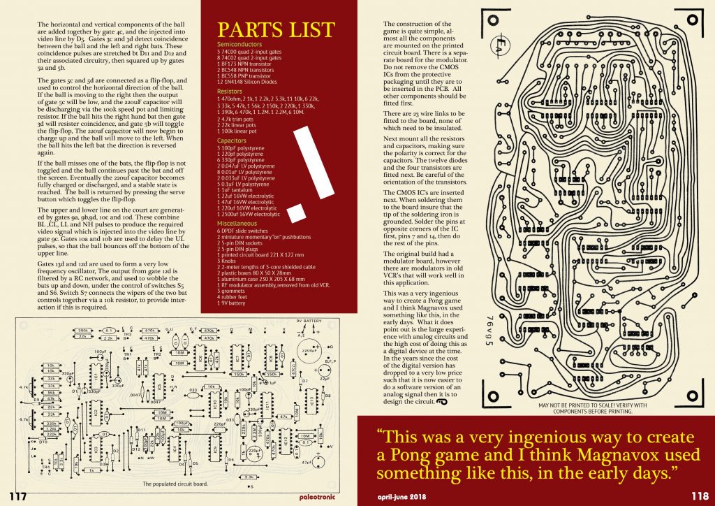
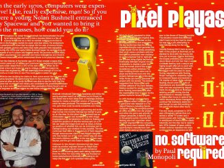
The construction of the game is quite simple, almost all the components are mounted on the printed circuit board. There is a separate board for the modulator. Do not remove the CMOS ICs from the protective packaging until they are to be inserted in the PCB. All other components should be fitted first.
There are 23 wire links to be fitted to the board, none of which need to be insulated.
Next mount all the resistors and capacitors, making sure the polarity is correct for the capacitors. The twelve diodes and the four transistors are fitted next. Be careful of the orientation of the transistors.
The CMOS IC’s are inserted next. When soldering them to the board insure that the tip of the soldering iron is grounded. Solder the pins at opposite corners of the IC first, pins 7 and 14, then do the rest of the pins.
The original build had a modulator board, however there are modulators in old VCR’s that will work well in this application.
This was a very ingenious way to create a Pong game and I think Magnavox used something like this, in the early days. What it does point out is the large experience with analog circuits and the high cost of doing this as a digital device at the time. In the years since the cost of the digital version has dropped to a very low price such that it is now easier to do a software version of an analog signal then it is to design the circuit.
PARTS LIST
Semiconductors
- 5 74C00 quad 2-input gates
- 8 74C02 quad 2-input gates
- 1 BF173 NPN transistor
- 2 BC548 NPN transistors
- 1 BC558 PNP transistor
- 12 1N4148 Silicon Diodes
Resistors
- 1 470ohm, 2 1k, 1 2.2k, 2 3.3k, 11 10k, 6 22k,
- 3 33k, 5 47k, 1 56k. 2 150k, 2 220k, 1 330k,
- 1 390k, 6 470k, 1 1.2M. 1 2.2M, 6 10M.
- 2 4.7k trim pots
- 2 22k linear pots
- 1 100k linear pot
Capacitors
- 5 100pF polystyrene
- 1 220pf polystyrene
- 6 330pF polystyrene
- 2 0.047uF LV polystyrene
- 8 0.01uF LV polystyrene
- 2 0.033uF LV polystyrene
- 5 0.1uF LV polystyrene
- 1 1uF tantalum
- 1 22uf 16VW electrolytic
- 1 47uf 16VW electrolytic
- 1 220uf 16VW electrolytic
- 1 2500uf 16VW electrolytic
Miscellaneous
- 6 DPDT slide switches
- 2 miniature momentary “on” pushbuttons
- 2 5-pin DIN sockets
- 2 5-pin DIN plugs
- 1 printed circuit board 221 X 122 mm
- 3 Knobs
- 2 2-meter lengths of 5-core shielded cable
- 2 plastic boxes 80 X 50 X 28mm
- 1 aluminium case 230 X 205 X 68 mm
- 1 RF modulator assembly, removed from old VCR.
- 3 grommets
- 4 rubber feet
- 1 9V battery
This is an advanced project, which requires soldering and circuit board printing.
Websites that describe how to solder:
https://www.build-electronic-circuits.com/how-to-solder/
http://www.instructables.com/id/How-to-solder/
Websites that describe DIY circuit-board printing methods:
http://www.instructables.com/id/Creating-Printed-Circuit-Boards-with-a-INKJET-Prin/
https://maker.pro/pcb/tutorial/how-to-make-a-printed-circuit-board-pcb
Also: YouTube!
Be the first to comment