
So you’ve invented a video camera (or a scanner) and you’ve got something to reproduce the picture on, but how do you get the signal from one to the other?
Well, you could do it over a wire. But neither Baird nor Farnsworth dreamt of “cable” television (although that would eventually become a thing) – they dreamt of wireless television. It’s in the name! They wanted anyone to be able to buy a television, go home (or wherever else they wanted to be), plug it into power and watch. So they had to deliver their video signals wirelessly – over radio waves.
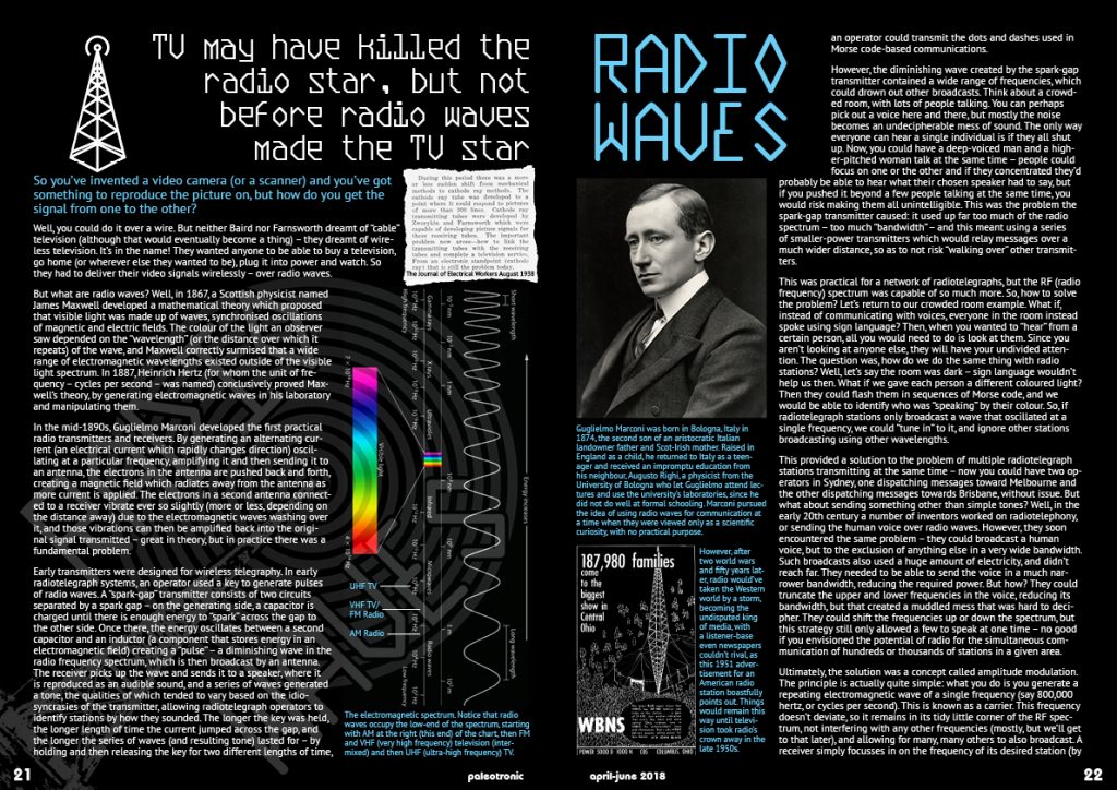
But what are radio waves? Well, in 1867, a Scottish physicist named James Maxwell developed a mathematical theory which proposed that visible light was made up of waves, synchronised oscillations of magnetic and electric fields. The colour of the light an observer saw depended on the “wavelength” (or the distance over which it repeats) of the wave, and Maxwell correctly surmised that a wide range of electromagnetic wavelengths existed outside of the visible light spectrum. In 1887, Heinrich Hertz (for whom the unit of frequency – cycles per second – was named) conclusively proved Maxwell’s theory, by generating electromagnetic waves in his laboratory and manipulating them.
In the mid-1890s, Guglielmo Marconi developed the first practical radio transmitters and receivers. By generating an alternating current (an electrical current which rapidly changes direction) oscillating at a particular frequency, amplifying it and then sending it to an antenna, the electrons in the antenna are pushed back and forth, creating a magnetic field which radiates away from the antenna as more current is applied. The electrons in a second antenna connected to a receiver vibrate ever so slightly (more or less, depending on the distance away) due to the electromagnetic waves washing over it, and those vibrations can then be amplified back into the original signal transmitted – great in theory, but in practice there was a fundamental problem.
Early transmitters were designed for wireless telegraphy. In early radiotelegraph systems, an operator used a key to generate pulses of radio waves. A “spark-gap” transmitter consists of two circuits separated by a spark gap – on the generating side, a capacitor is charged until there is enough energy to “spark” across the gap to the other side. Once there, the energy oscillates between a second capacitor and an inductor (a component that stores energy in an electromagnetic field) creating a “pulse” – a diminishing wave in the radio frequency spectrum, which is then broadcast by an antenna. The receiver picks up the wave and sends it to a speaker, where it is reproduced as an audible sound, and a series of waves generated a tone, the qualities of which tended to vary based on the idiosyncrasies of the transmitter, allowing radiotelegraph operators to identify stations by how they sounded. The longer the key was held, the longer length of time the current jumped across the gap, and the longer the series of waves (and resulting tone) lasted for – by holding and then releasing the key for two different lengths of time, an operator could transmit the dots and dashes used in Morse code-based communications.
However, the diminishing wave created by the spark-gap transmitter contained a wide range of frequencies, which could drown out other broadcasts. Think about a crowded room, with lots of people talking. You can perhaps pick out a voice here and there, but mostly the noise becomes an undecipherable mess of sound. The only way everyone can hear a single individual is if they all shut up. Now, you could have a deep-voiced man and a higher-pitched woman talk at the same time – people could focus on one or the other and if they concentrated they’d probably be able to hear what their chosen speaker had to say, but if you pushed it beyond a few people talking at the same time, you would risk making them all unintelligible. This was the problem the spark-gap transmitter caused: it used up far too much of the radio spectrum – too much “bandwidth” – and this meant using a series of smaller-power transmitters which would relay messages over a much wider distance, so as to not risk “walking over” other transmitters.
This was practical for a network of radiotelegraphs, but the RF (radio frequency) spectrum was capable of so much more. So, how to solve the problem? Let’s return to our crowded room example. What if, instead of communicating with voices, everyone in the room instead spoke using sign language? Then, when you wanted to “hear” from a certain person, all you would need to do is look at them. Since you aren’t looking at anyone else, they will have your undivided attention. The question was, how do we do the same thing with radio stations? Well, let’s say the room was dark – sign language wouldn’t help us then. What if we gave each person a different coloured light? Then they could flash them in sequences of Morse code, and we would be able to identify who was “speaking” by their colour. So, if radiotelegraph stations only broadcast a wave that oscillated at a single frequency, we could “tune in” to it, and ignore other stations broadcasting using other wavelengths.
This provided a solution to the problem of multiple radiotelegraph stations transmitting at the same time – now you could have two operators in Sydney, one dispatching messages toward Melbourne and the other dispatching messages towards Brisbane, without issue. But what about sending something other than simple tones? Well, in the early 20th century a number of inventors worked on radiotelephony, or sending the human voice over radio waves. However, they soon encountered the same problem – they could broadcast a human voice, but to the exclusion of anything else in a very wide bandwidth. Such broadcasts also used a huge amount of electricity, and didn’t reach far. They needed to be able to send the voice in a much narrower bandwidth, reducing the required power. But how? They could truncate the upper and lower frequencies in the voice, reducing its bandwidth, but that created a muddled mess that was hard to decipher. They could shift the frequencies up or down the spectrum, but this strategy still only allowed a few to speak at one time – no good if you envisioned the potential of radio for the simultaneous communication of hundreds or thousands of stations in a given area.
Ultimately, the solution was a concept called amplitude modulation. The principle is actually quite simple: what you do is you generate a repeating electromagnetic wave of a single frequency (say 800,000 hertz, or cycles per second). This is known as a carrier. This frequency doesn’t deviate, so it remains in its tidy little corner of the RF spectrum, not interfering with any other frequencies (mostly, but we’ll get to that later), and allowing for many, many others to also broadcast. A receiver simply focusses in on the frequency of its desired station (by using a bandpass filter to remove other frequencies), like staring at a single person speaking with sign language in a crowded room. But at this point they’re just signing the same one thing over and over again, “bird”. How can they communicate with us if they can only sign “bird” (beyond informing us that they have a thing for birds?) Well, that’s where modulation comes in.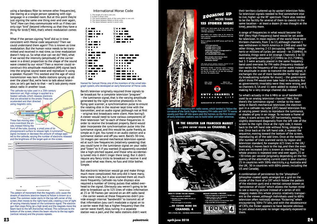 What if the person signing “bird” did so in time consistent with Morse code sequences? Then we could understand them again! This is known as time modulation. But the human voice needs to be transmitted and received in real-time, so time modulation doesn’t help us. So what else can we do? Well, what if we varied the intensity (amplitude) of the carrier wave in a direct proportion to the shape of the sound wave created by our voice? Then a receiver could reconstruct this amplitude modulated (AM) signal back into the original sound wave and reproduce it using a speaker. Huzzah! This worked and the age of voice transmission was born. Radio stations sprung up all over the place! But, we’re here to talk about television, so let’s get back to that – we’ll talk plenty more about radio in another issue.
Baird’s televisor originally required three signals to be broadcast for a complete television “program” – the luminance signal, that is the varying amplitude generated by the light-sensitive photocells in his flying spot scanner; a synchronisation pulse to ensure the rotating disk in the receiver kept time with the transmitter; and an audio signal (although not at first – original test broadcasts were silent. How boring!) A viewer would need to tune various components of their television “set” to each of these frequencies in order to receive the broadcast properly. Baird would later incorporate the synchronisation pulse into the luminance signal, and this would be, quite frankly, as simple as it got. You tuned in an audio station and a luminance station and off you went. Baird’s 30-line, 16 images-per-second mechanical television operated at such low frequencies (relatively speaking) that you could tune in the luminance signal on your radio and “listen” to it if you wanted (it apparently sounded like a high-pitched squeal, and those who accidentally tuned into it didn’t linger there long). But it didn’t require any fancy tricks to broadcast or receive it and just used what was there, no fuss and little bother. Simple.
But electronic television would go and make things much more complicated. Not only did it have many, many more lines, but it also scanned them all much more frequently. Cathode-ray tube displays also required a number of timing pulses that added overhead to the signal. Obviously you weren’t going to be able to broadcast up to 525 lines of video information at 25 or 30 frames per second on an AM radio band – the carrier waves at those frequencies didn’t provide enough internal “bandwidth” to transmit all of that information (you can’t modulate a signal on to a carrier wave that has a higher frequency than the carrier wave itself). Also, tuning in a separate audio station was a pain, and the radio stations didn’t want their territory cluttered up by upstart television folks. So television signals needed to find somewhere else to live, higher up the RF spectrum. There also needed to be the facility for several of them to coexist in the same location – at least a dozen (it was thought at the time), possibly more.
A range of frequencies in what would become the VHF (Very High Frequency) band would be set aside for television. In most regions of the world there were thirteen channels, from 1 to 13, although channel 1 was withdrawn in North America in 1948 and used for other things, leaving 2-13 (occupying 48MHz – megahertz or millions of cycles per second – to 216MHz). In Australia, things were a bit strange. Channels 1 to 10 were originally allocated (57.25MHz to 215.75MHz), but 1-3 were actually placed in the same frequency band used overseas for FM radio (frequency modulation varies the frequency of the carrier wave instead of the amplitude in order to transmit the audio signal; it exchanges the use of more bandwidth for better quality broadcasting suitable for music) – the government didn’t think FM would ever take hold in Australia. But as governments invariably were they were wrong, and so channels 0, 5A and 11 were added to replace 1 to 3, making for a very strange channel dial indeed!
So what’s actually in the 6 MHz or so of bandwidth used by an analog television channel? Well, first there’s the luminance signal – similar to the neon lamp in Baird’s mechanical television, the electron gun in a cathode-ray tube (CRT)-based television fires at varying power levels to reproduce the luminance, or shades of grey in an image. To recreate a frame of video, it scans across the CRT horizontally, moving slightly downward diagonally from the left side of the screen to the right. Once at the right side, it moves back to the left hand side without firing, skipping a line. Once back at the left hand side, it repeats the sequence, moving toward the bottom of the screen, reproducing all of the odd lines. Once at the bottom (the number of lines scanned varies by region and television standard, for example 625 lines in the UK/Australia), it moves back to the top, and then the even lines are recreated (this is known as interlacing). The whole process is repeated over and over again, 25 or ~30 times per second (originally depending on the frequency of the alternating current used in your country: 25 in countries with 50Hz electricity, e.g. Australia and the UK; 30 in countries with 60Hz power, including the US and Canada).
A combination of persistence by the “phosphors” (phosphor-coated spots arranged on a grid on the inside of the front of a CRT which follow the pattern of the electron gun) and a mental concept known as “persistence of vision” which allows the human mind to see a moving picture instead of a series of still images) makes this whole process relatively transparent to the viewer, although individuals used to 60Hz television often notice(d) obvious “flickering” when encountering 50Hz TV sets, and with the obsolescence of CRTs, the flicker appears to have become obvious to just about everyone no longer regularly exposed to them.
In black-and-white (actually grayscale, not monochrome) broadcasts, the luminance signal (which told the CRT’s electron gun what to do) was initially made up of a series of horizontal lines comprising the following components: First, the “front porch” is a brief period at 300mV (millivolts) which allows the electron gun to stop firing (to avoid interference during the horizontal “retrace”, or return to the left side of the screen). Second, the “sync pulse” (0mV) ensures the electron gun gets into place to start scanning the next line at the right time. Third, the “back porch” warms up the electron gun to get it ready to fire the next line, which it then does (at levels fluctuating from 300 to 1000mV, corresponding to the varying brightness of the line). Once at the bottom of the screen, the vertical blanking interval (VBI) gives time to allow the electron gun to return to the top of the screen. The luminance signal was modulated using amplitude modulation (AM), with audio broadcast as an FM signal alongside it. Together they filled up the bandwidth available in the channel, for the best broadcast quality and range possible.
But what of colour TV? Once it became viable, broadcasters were reluctant to broadcast two signals, due to expense and regulations, and so to encourage adoption a method had to be found to allow black-and-white televisions to continue to receive a luminance signal while colour televisions also received the information necessary to reproduce colour – but only using the allocated channel bandwidth. At first, television scientists cursed their decision to fill up the channel bandwidth with the AM luminance signal, but they were stuck with it! However, while researching a solution they discovered that there was a certain amount of (mostly) empty space in the frequencies that made up the luminance signal, in the area that made up the really bright parts of the picture (and where a small amount of interference from a colour signal wouldn’t be noticed by black-and-white TVs).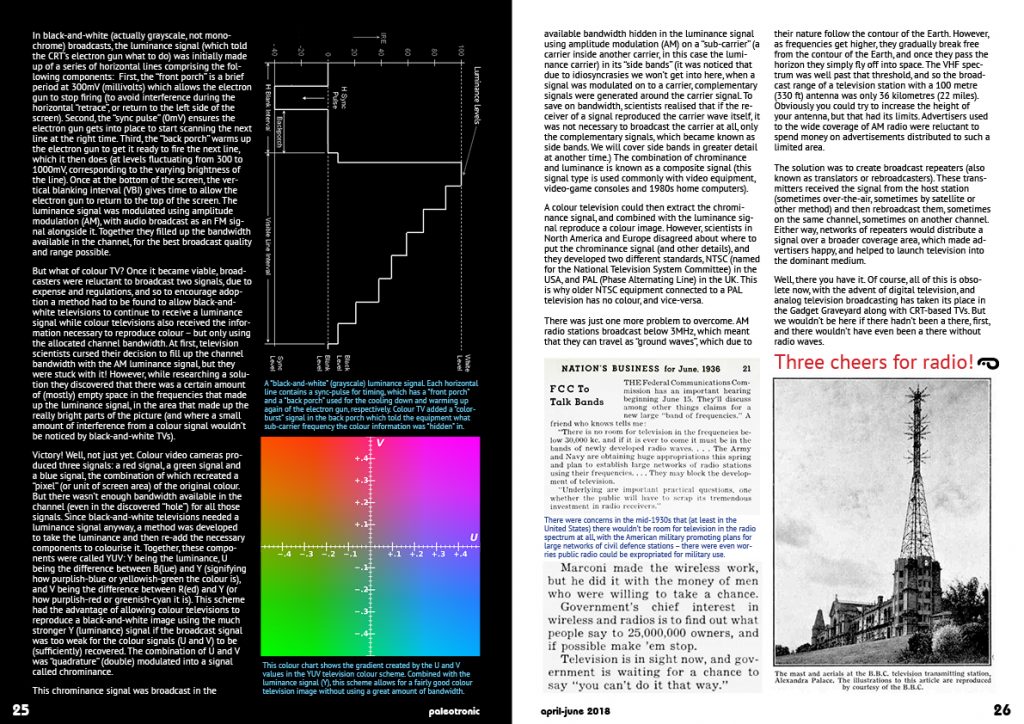 Victory! Well, not just yet. Colour video cameras produced three signals: a red signal, a green signal and a blue signal, the combination of which recreated a “pixel” (or unit of screen area) of the original colour. But there wasn’t enough bandwidth available in the channel (even in the discovered “hole”) for all those signals. Since black-and-white televisions needed a luminance signal anyway, a method was developed to take the luminance and then re-add the necessary components to colourise it. Together, these components were called YUV: Y being the luminance, U being the difference between B(lue) and Y (signifying how purplish-blue or yellowish-green the colour is), and V being the difference between R(ed) and Y (or how purplish-red or greenish-cyan it is). This scheme had the advantage of allowing colour televisions to reproduce a black-and-white image using the much stronger Y (luminance) signal if the broadcast signal was too weak for the colour signals (U and V) to be (sufficiently) recovered. The combination of U and V was “quadrature” (double) modulated into a signal called chrominance.
This chrominance signal was broadcast in the available bandwidth hidden in the luminance signal using amplitude modulation (AM) on a “sub-carrier” (a carrier inside another carrier, in this case the luminance carrier) in its “side bands” (it was noticed that due to idiosyncrasies we won’t get into here, when a signal was modulated on to a carrier, complementary signals were generated around the carrier signal. To save on bandwidth, scientists realised that if the receiver of a signal reproduced the carrier wave itself, it was not necessary to broadcast the carrier at all, only the complementary signals, which became known as side bands. We will cover side bands in greater detail at another time.) The combination of chrominance and luminance is known as a composite signal (this signal type is used commonly with video equipment, video-game consoles and 1980s home computers).
A colour television could then extract the chrominance signal, and combined with the luminance signal reproduce a colour image. However, scientists in North America and Europe disagreed about where to put the chrominance signal (and other details), and they developed two different standards, NTSC (named for the National Television System Committee) in the USA, and PAL (Phase Alternating Line) in the UK. This is why older NTSC equipment connected to a PAL television has no colour, and vice-versa.
There was just one more problem to overcome. AM radio stations broadcast below 3MHz, which meant that they can travel as “ground waves”, which due to their nature follow the contour of the Earth. However, as frequencies get higher, they gradually break free from the contour of the Earth, and once they pass the horizon they simply fly off into space. The VHF spectrum was well past that threshold, and so the broadcast range of a television station with a 100 metre (330 ft) antenna was only 36 kilometres (22 miles). Obviously you could try to increase the height of your antenna, but that had its limits. Advertisers used to the wide coverage of AM radio were reluctant to spend money on advertisements distributed to such a limited area.
The solution was to create broadcast repeaters (also known as translators or rebroadcasters). These transmitters received the signal from the host station (sometimes over-the-air, sometimes by satellite or other method) and then rebroadcast them, sometimes on the same channel, sometimes on another channel. Either way, networks of repeaters would distribute a signal over a broader coverage area, which made advertisers happy, and helped to launch television into the dominant medium.
Well, there you have it. Of course, all of this is obsolete now, with the advent of digital television, and analog television broadcasting has taken its place in the Gadget Graveyard along with CRT-based TVs. But we wouldn’t be here if there hadn’t been a there, first, and there wouldn’t have even been a there without radio waves.
Three cheers for radio!
Be the first to comment